DualBand Wi-Fi Telemetry Radio - M10114 
Have you ever lost telemetry due to 2.4 WiFi band saturation?
We developed this radio attending our customers requests for a 5 GHz capable telemetry radio.
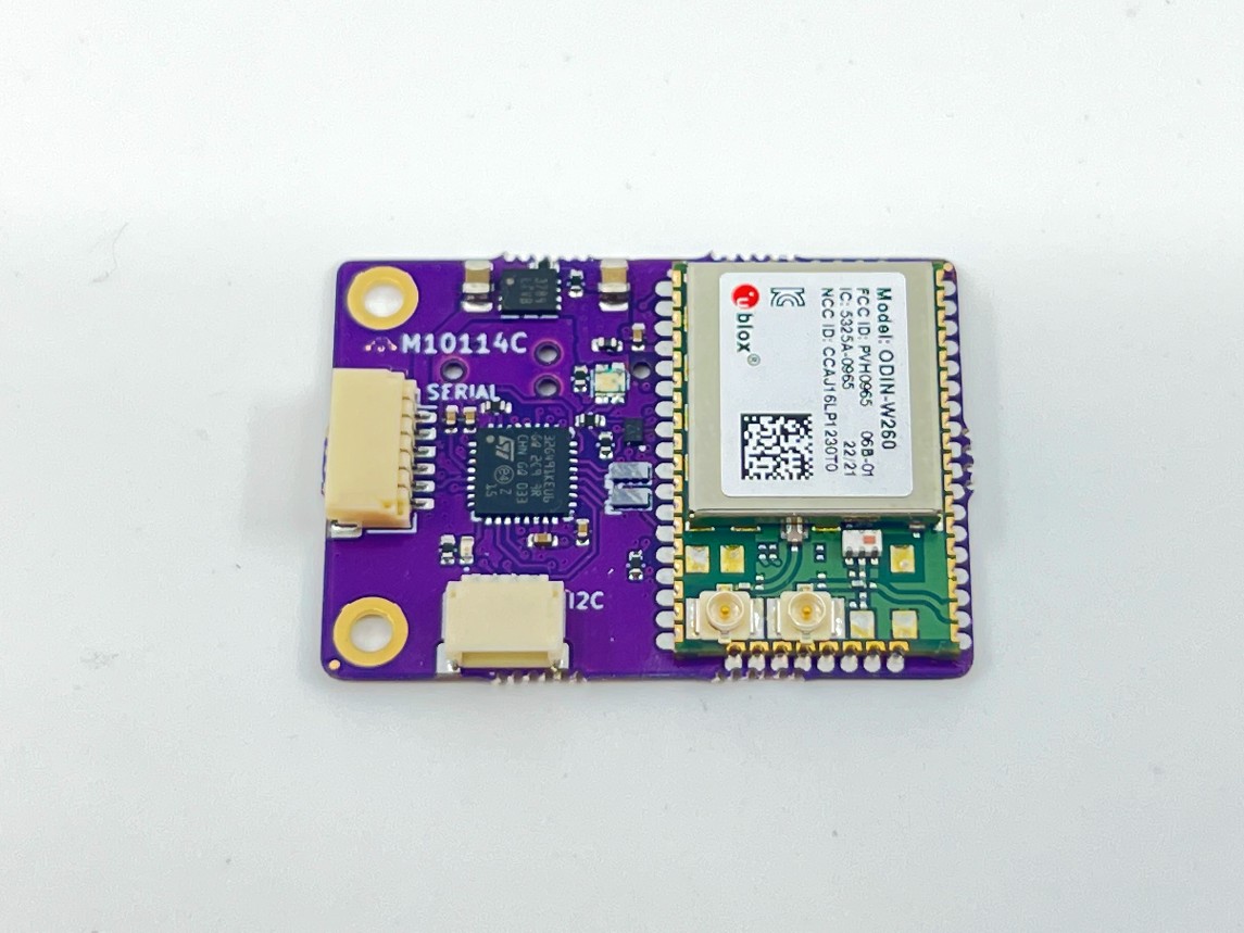
The 3DR DualBand Wi-Fi radio is developed around the UBLOX ODIN-W260 module. It comes with a JST-SH 6 pin connector allowing you to easily integrate with existing autopilots. Supports UDP or TCP connections and can be configured as Station or Access Point.
The 3DR DualBand Wi-Fi radio is NDAA compliant.
Purchase Wifi Module
Typical Usage
The default parameters are:
| WiFi mode | AP |
|---|---|
| UDP | enabled |
| Local port | 14550 |
| Auto reply | enabled |
| SSID | mRo_wifi |
| Password | controlZero |
| IP address | 192.168.2.1 |
| UART baud rate | 115200 |
| MavLink | disabled |
A WiFi network will be created automatically when mRo DualBand Wi-Fi radio is powered on.
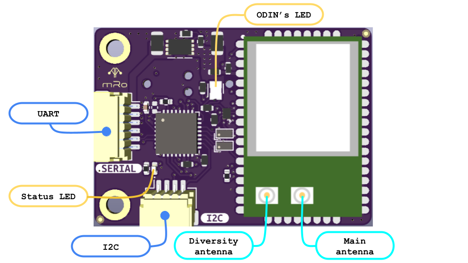
You will find a JST-SH 6 pin to JST-GH 6 pin cable included, which is the standard for our boards. Connect the mRo DualBand Wi-Fi radio’s UART port to any of your autopilot’s telemetry ports.
Your autopilot’s telemetry port should have a baud rate of 115200(115 for ArduPilot).
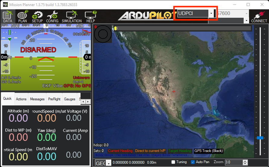
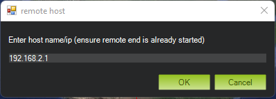
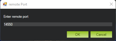
After powering on the radio, wait for the Status LED to turn solid green. Then connect your computer to “mRo_wifi” network using “controlZero” as password. Open Mission Planner and select UDPCI as the connection type. Enter 192.168.2.1 when asked for the host name/ip, and 14550 as the remote port.
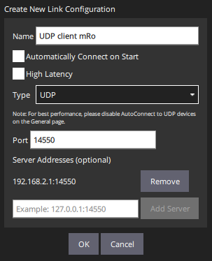
If you use QGroundControl, add a new communication link and configure it as in the next image:
Antennas
The DualBand Wi-Fi radio has two antenna UFL coaxial connectors. The main antenna connector supports dual-band WiFi. The diversity antenna connector adds support for 2.4 GHz band Wi-Fi (2×2 MIMO). So, if you want to use the 2.4 GHz band, add a second antenna for better performance.
The main antenna should always be connected when the mRo DualBand Wi-Fi radio is on. See the previous diagram to identify the connectors.
AT Commands
mRo DualBand Wi-Fi radio can be configured using AT commands through Wi-Fi or UART communication.
Using WiFi
You can use any UDP client app to connect to mRo DualBand Wi-Fi radio.
For Windows users, Hercules is a good option.
For Linux and Mac users, we recommend NetCat. Use this command nc -u 192.168.2.1 14550 to establish an UDP connection.
Warning
Note that if you change any of the network parameters, you would have to make the corresponding adjustments to reach the module through Wi-Fi.
Using UART
If you want to change the default settings using the UART port, you will have to configure the mRo DualBand Wi-Fi radio before connecting the autopilot. You can use the 3DR USB FTDI Serial to JST-GH to connect the mRo DualBand Wi-Fi radio to your computer.
Any serial terminal program can be used to establish communication with the mRo DualBand WiFi radio.
Windows users can use RealTerm or Hercules .
For Linux and Mac users, Cutecom is a good option.
Available commands:
| Command | Action |
|---|---|
| +++++ | enables AT mode |
| ATB | display bootloader version |
| ATI | display parameters values |
| ATH | display commands information |
| ATO | exit AT mode |
| ATSX? | display parameter X |
| ATSX=Y | set parameter X equal to Y |
| ATSH | display parameters description |
| AT&D | set parameters to default |
| AT&W | save parameters |
All parameters have a numeric id used to change their values. See the following table:
| ID | Name | Posible values | Description |
|---|---|---|---|
| S0 | Firmware version | Can not be changed. | |
| S1 | Debug mode* | 0 | Debug mode disabled |
| 1 | Debug mode enabled | ||
| S2 | WiFi mode | 0 | WiFi disabled |
| 1 | Access Point | ||
| 2 | Station | ||
| S3 | Connection protocol | 0 | UDP connection |
| 1 | TCP connection | ||
| S4 | Auto reply | Used for UDP connection only. | |
| 0 | Reply to port specified in S10. | ||
| 1 | UDP server like behavior. Reply to source port of UDP packet. | ||
| S5 | WiFi channel | Used in AP mode only | |
| 1 to 11 | 2.4 GHz band | ||
| 36 to 64 | 5 GHz band | ||
| 100 to 144 | 5 GHz band | ||
| 149 to 177 | 5 GHz band | ||
| S6 | DHCP | Used in station mode only | |
| 0 | Use static IP specified in S7. | ||
| 1 | Get IP from the router's DHCP. | ||
| S7 | Local IP | Local IP (IPV4). Used if AP mode is active or if Station mode is active and DCHP is disabled. | |
| S8 | Local port | Listening port | |
| S9 | Peer's IP | Peer's IP (IPV4). Used if UDP is active and Auto reply is disabled. | |
| S10 | Remote port | Peer's listening port. Used if UDP is active and Auto reply is disabled. | |
| S11 | Subnet mask | Used in AP mode. It is also used to recalculate peer's IP when UDP is active and Auto mode is disabled | |
| S12 | Gateway | Used in AP mode. | |
| S13 | IP Filter | Only used if UDP connection is active and Auto reply mode is disabled. | |
| 0 | Use peer's IP as it is. | ||
| 1 | Use local network's prefix for peer's IP. | ||
| S14 | SSID AP | Network name. Used in AP mode only. 16 characters max. This is the network you should connect your computer to. | |
| S15 | Password AP | Network password. Used in AP mode only. 16 characters max. This is the password your should use when connecting your computer (WPA2). | |
| S16 | SSID Station | Used in Station mode only. 16 characters max. This is your router network's name. | |
| S17 | Password Station | Used in Station mode only. 16 characters max. This is your router network's password(WPA2). | |
| S18 | UART baud rate | UART baud rate. 921600 max**. | |
| S19 | Module mode | 0 | Bridge mode |
| 1 | MavLink mode. Only MavLink messages will be forwarded. | ||
| S20 | Data mode | 0 | Data mode disabled. ODIN module will not forward any data even if it's connected to the network. All UART messages will be handled by ODIN's command mode.*** |
| 1 | Data mode enabled. |
*Debug mode is only available through UART communication.
**115200 is the maximum constant baud rate with no data loss. ODIN UART communication works at 115200 baud rate.
***Disabling Data mode is only recommended if you use the mRo DualBand Wi-Fi radio as a dev board for the ODIN module.
Configuration example
Let’s say you want to connect your mRo DualBand Wi-Fi radio as a station to an already existing Wi-Fi network. You would have to send the following commands:
Command: +++++
Response: mRo AT Command mode
Command: ATS2=2
Response: mRo OK
Command: ATS16=my_ssid_name
Response: mRo OK
Command: ATS17=my_password
Response: mRo OK
Command: ATS6=1
Response: mRo OK
Command: AT&W
Response: Params flashed successfully.
mRo OK
Command: ATO
Response: mRo OK
In the next power cycle your mRo DualBand Wi-Fi radio should connect to your network. Use the IP assigned by your router to establish an UDP connection.
You can also use a static IP if you know your router’s network beforehand. Set S7 to the desired IP and S6 to 0.
Use the ATI command to check that you typed the SSID and password correctly. Otherwise you will not be able to connect to your mRo DualBand Wi-Fi radio via Wi-Fi again.
JST-SH Pinout
| Pin | Signal | Volt |
|---|---|---|
| 1 (Red) | VCC IN | 5V |
| 2 (Black) | RX | 3.3V |
| 3 (Black) | TX | 3.3V |
| 4 (Black) | RTS | 3.3V |
| 5 (Black) | CTS | 3.3V |
| 6 (Black) | GND | GND |
Return to default parameters
If you changed some parameters and now you can not connect to your mRo DualBand Wi-Fi radio, you can always go back to the default parameters.
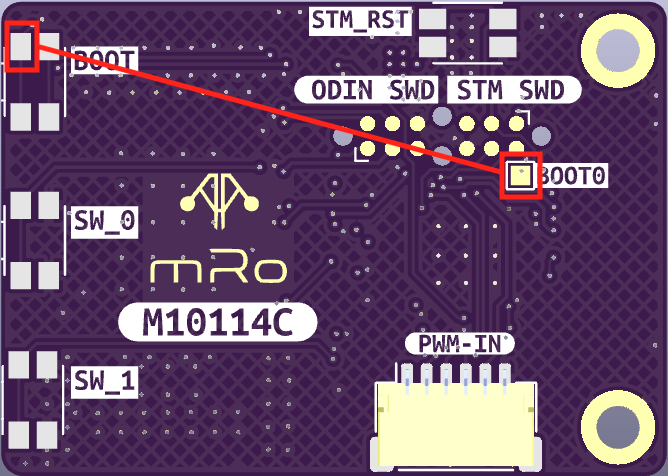
After you power on the radio and while the Status LED is still blinking, shortcut the BOOT0 square path in the back of the board with the path closest to the corner under the label of BOOT.
Do NOT do it before the Status LED start blinking. You will have a window of at least 5 seconds after you power on the radio.
If you do it right, the Status LED should stop blinking and turn solid green immediately after.
Power cycle the mRo DualBand Wi-Fi radio for the default parameters to take effect.
Update firmware
Firmware update is only possible through UART communication using the mRo Programmer Utility. It is available for Windows, MacOS and Linux.
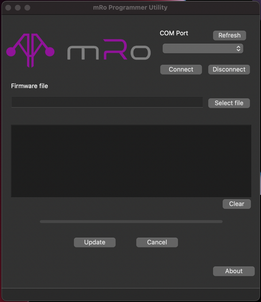
Connect the mRo DualBand Telemetry Radio to your computer and click on the Refresh button. Select the corresponding device on the drop down list and click on Connect. The output should be similar to the following image:
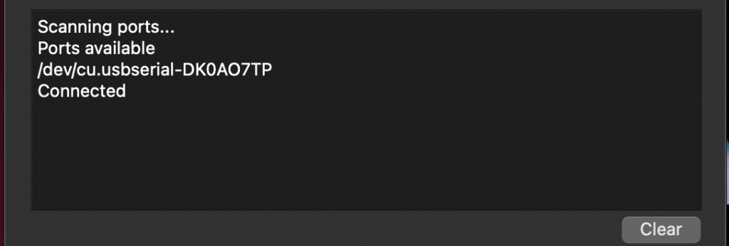
Then select the binary file using the Select file button, or type the absolute path to the file if you prefer. Next click on the Update button and wait for the program to finish.
The output should be similar to the following image:
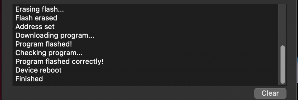
Verify that the message “Program flashed correctly!” is shown in the console.
Update ODIN's firmware
Do not update ODIN’s firmware if you do not have to. If you do it, is under your own risk.
You will have to disable WiFi mode (ATS2=0) and do a power cycle. After that, you will be able to use s-center program provided by u-blox to upload the new firmware. Select None for flow control when configuring the port in s-center.
STEP File
Programmer Utility
- 1_0_3_ProgrammerUtility_win_x64
- 1_0_3_ProgrammerUtility_macos.app
- 1_0_3_ProgrammerUtility_linux_x86_64
- 1_0_3_ProgrammerUtility_linux_aarch64.AppImage