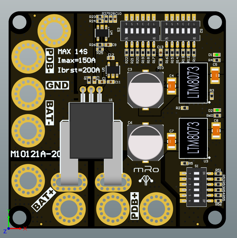
High Current Power Module - M10121 
The sensor is based on the Allegro ACS758 analog high current Hall-effect sensor, which provides a low-offset and 100 μΩ resistance for low power loss and high inrush current capabilities.
Our M10121 board has two LTM8073 supplies for superb efficiency and uncompromised power delivery, one is fixed at 5.2V and the other has a selectable output from 5 to 12 V, more details below.
Integrated capacitors reduce voltage noise, however we still recommend to install the included electrolytic capacitor to compensate for long battery wire lengths and motor noise.
This board comes with a set of dip switches to optimize the range of the voltage ADC, given that the range is for up to 14S, this allows using lower cell counts without compromising the voltage indicator's precision.
Specifications
Electrical
- 58.8V 14S LiPo VinMAX
- 150 Amps Continuous- 200 Amps Max Current Sensing
- 5.3V, 3A power supply
- 5V, 6V, 7V, 8V, 9V, 12V selectable 3A power supply.
Mechanical
- Board Weight: 24.44g (0.862 oz)
- Board Dimensions:
- 50mm x 50mm (1.9685" x 1.9685")
Graphical datasheet
This board is self-documenting, however these images and tables may help setting up the dip switches and configuring the parameters adequately.
S1 switch group
| Switch # | Vsel |
|---|---|
| 1 | 5V |
| 2 | 6V |
| 3 | 7V |
| 4 | 8V |
| 5 | 9V |
| 6 | 12V |
S2-S3 switch group
| Switch # | Cell count | VOLT_MULT |
|---|---|---|
| S2-1 | 3S | 3.81 |
| S2-2 | 4S | 5.09 |
| S2-3 | 5S | 6.36 |
| S2-4 | 6S | 7.63 |
| S2-5 | 7S | 8.91 |
| S2-6 | 8S | 10.18 |
| S3-1 | 9S | 11.45 |
| S3-2 | 10S | 12.73 |
| S3-3 | 11S | 14.0 |
| S3-4 | 12S | 15.27 |
| S3-5 | 13S | 16.54 |
| S3-6 | 14S | 17.81 |
VOLT_MULT may vary depending on the ADC input circuit of the autopilot it is attached to, so fine tuning the value is encouraged for optimum accuracy.
Warning
Make sure only one switch from each group is ON at a time.
Parameters:
- Set
BATT_MONITORx = 4, then reboot. - Set
BATT_VOLT_MULT =value of the table depending on the cell count and active switch. - Set
BATT_AMP_PERVLT = 60.5
Pinout description
6-pin Molex Clik-Mate
PWR Connector
| Pin | Color | Signal | TTL/Voltage Level |
|---|---|---|---|
| 1 | red | VCC | 5.3V |
| 2 | black | VCC | 5.3V |
| 3 | black | CURRENT | 3V3 |
| 4 | black | VOLTAGE | 3V3 |
| 5 | black | GND | N/A |
| 6 | black | GND | N/A |
Tip
A Molex Clik-Mate to JST-GH cable is provided to maximize compatibility.
4-pin Molex Clik-Mate
Additional power supply
| Pin | Color | Signal |
|---|---|---|
| 1 | red | Vsel |
| 2 | black | Vsel |
| 3 | black | GND |
| 4 | black | GND |
Downloads
[Designed and assembled in USA]