Quad Zero Kit - Assembly Guide
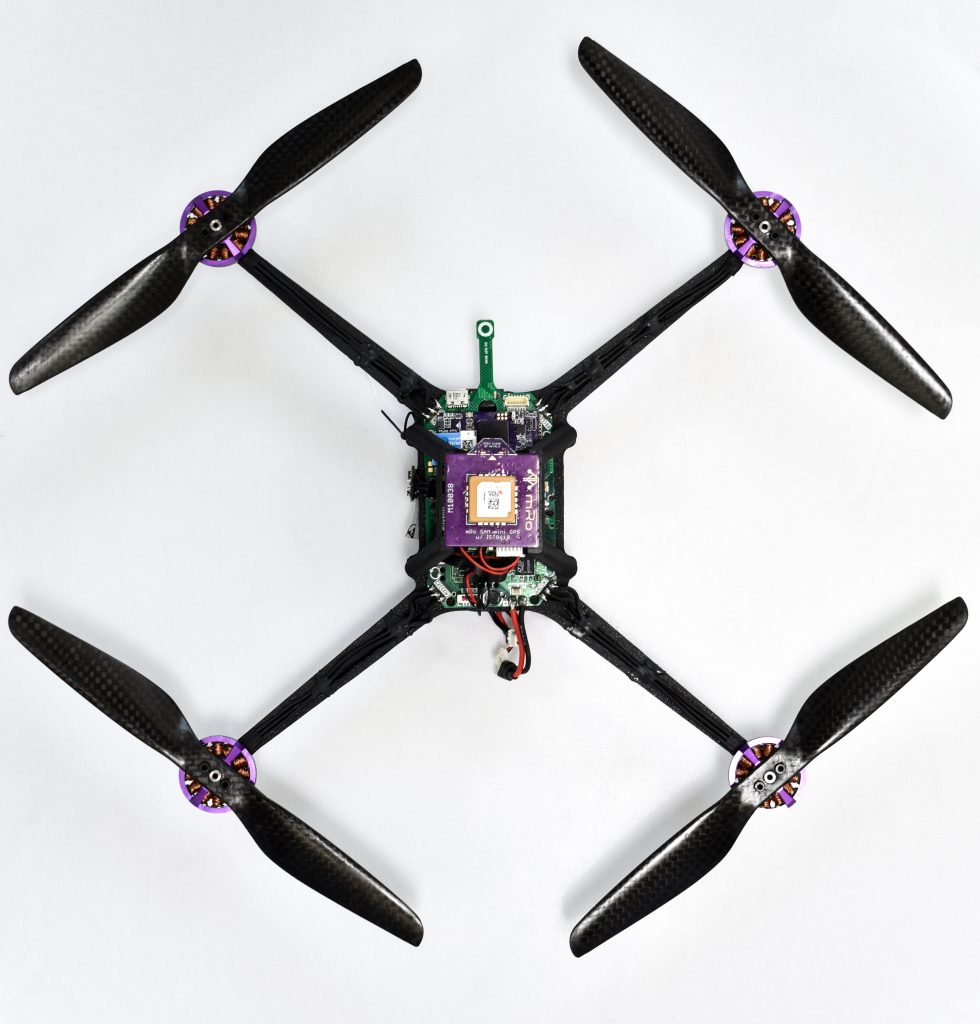
The Quad Zero Kit is a lightweight (<250g) platform with a 3D-printable frame, agile flying envelope with extended flight times yet simple to setup. It is powered by our most popular flight controller yet, the Control Zero H7 OEM on top of custom made motors and a carrier board that includes power monitoring, integrated ESC module, Time-of-Flight sensor for precision landing (Z-axis), and additional ports to support any OSD, GPS, CAN, telemetry and any other payload peripherals.
This kit is perfect as a development platform, educational, or even a light show drone – light and FPV pod coming soon!
We put together this guide to help you get up and running with your QZKit platform as fast as possible. Please note that this build may take anywhere from 3 hrs to several sessions depending on your particular experience.
What's Included
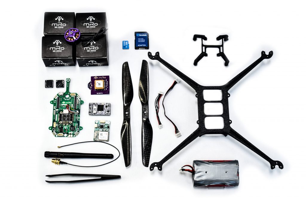
Please make sure you have all the parts listed below, if something is missing or you have any questions please do not hesitate to contact us. Spare or extra parts are available individually following the links.
| Qty | Part No. | Description |
|---|---|---|
| 1 | Quad Zero frame | |
| 1 | GPS mount | |
| 4 | 2-56x 3/16 Nylon socket head screws | |
| 2 | 2-56x ⅛ Nylon socket head screws | |
| 4 | M2-2202 | 3DR brushless motors |
| 12 | M1.6 x 4mm black oxide screws. (motor mounting screws) | |
| 8 | M2 x 4mm black oxide screws. (propeller mounting screws) | |
| 2 | CW/CCW propeller sets | |
| 1 | M10112 | Quad Zero Carrier Board |
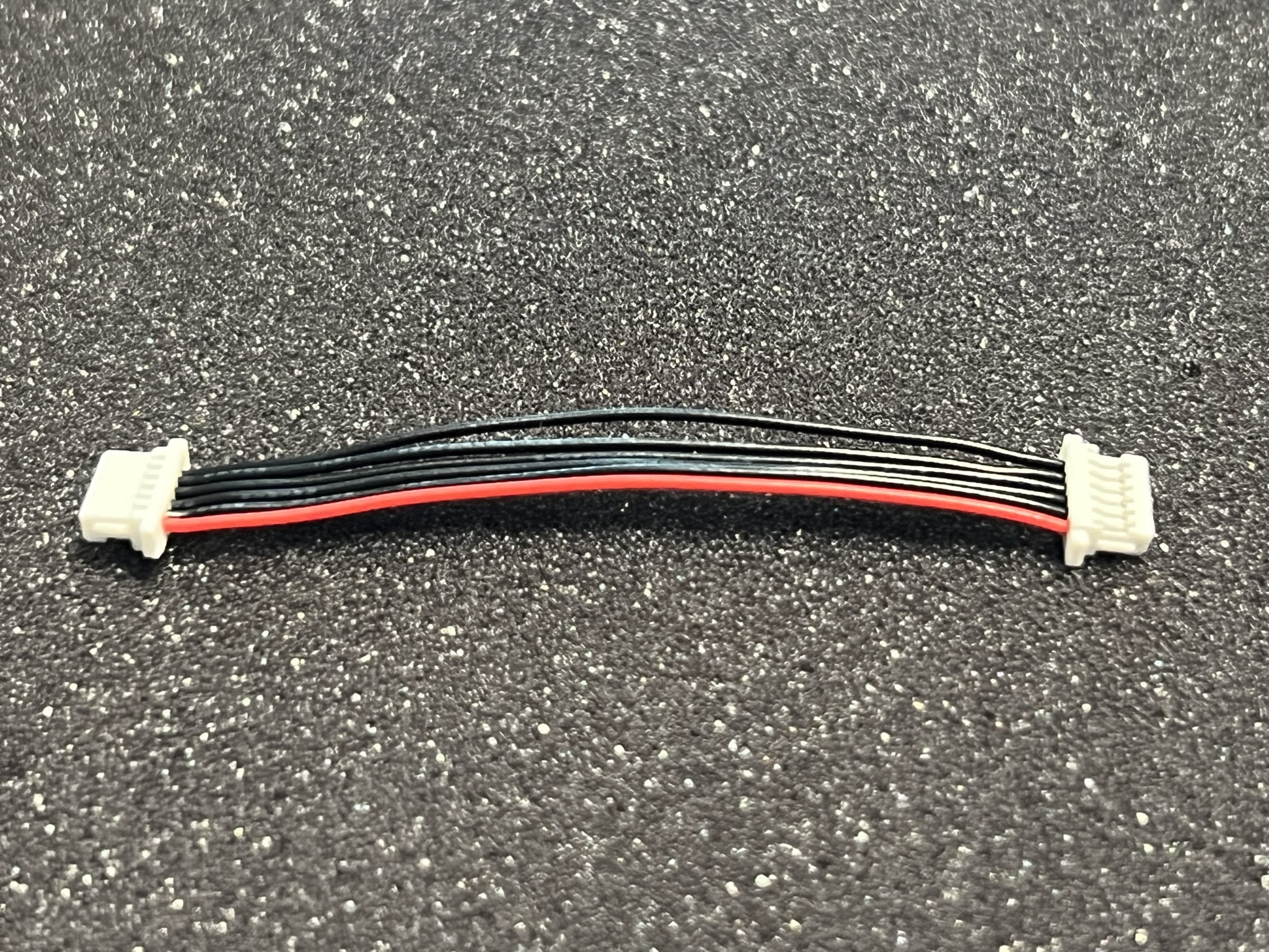
| 3 | MRC-0243 | JST-GH 6 to JST-SH 6 cables |
| 1 | BT2.0 pigtail | |
| 2 | ½”x½”x1/10” vibration dampers | |
| 1 | M10059 | Control Zero H7 OEM |
| 1 | SD Card | |
| 1 | Plastic tweezers | |
| 1 | M10038 | Med size SAM GPS |
| 1 | EMI Shield | EMI shielding to go between GPS and WiFi |
| 1 | ExpressLRS radio receiver | |
| 1 | liion-2s | Quad Zero 2S 4200mAh Battery Pack |
| 1 | XT60-BT2.0 adapter | |
| 1 | Balance port adapter (JST-SH 3 to JST-XH 3) |
If you ordered the optional Dual-Band WiFi Telemetry Radio:
| Qty | Part | Description |
|---|---|---|
| 1 | M10114C | Dual Band WiFi Telemetry radio |
| 1 | Molex WiFi na | |
| 1 | MRC-0291 | JST-SH 4 short cable |
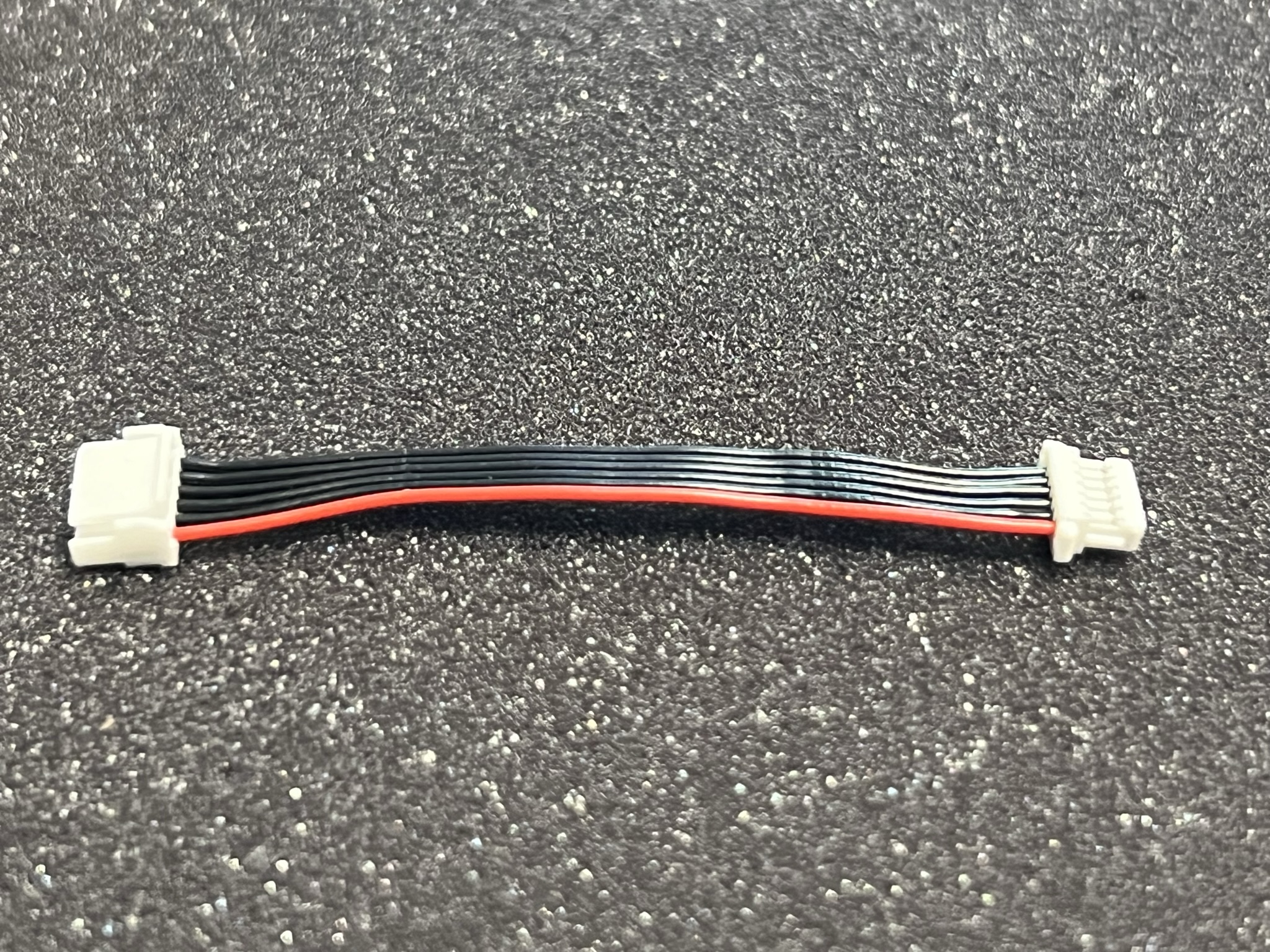
| 1 | MRC-0292 | JST-SH 6 short cable |
Required tools
-
M1.5 hex driver
-
M2 hex driver
-
Hobby knife
-
CA glue
-
Accelerator - optional
-
Soldering iron
-
Solder wire
-
Double-sided tape - 3M VHB recommended
-
Prop balancer - optional
-
Scissors - optional
Extra resources
-
ExpressLRS compatible transmitter
-
Ground station - any laptop, tablet or embedded device running Mission Planner or QGC
Step 1 - Attach motors to the frame
Allocate the following materials:
- 12x M1.6x4mm screws (included inside the motors)
- 4x M2-2202 brushless motors
- Quad Zero frame
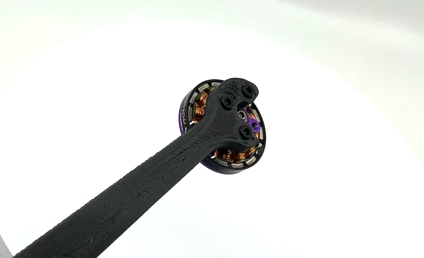
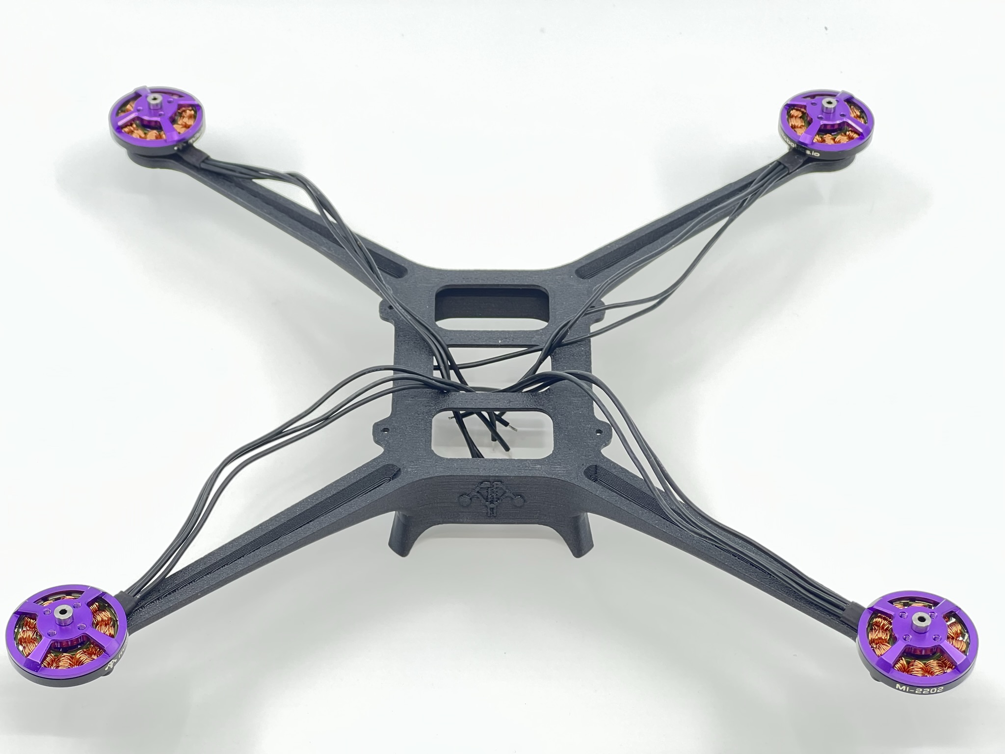
Take one M2-2202 brushless motor from its box and make sure the rotor can spin freely. Screw it in place with 3x M1.6x4mm hex screws with your M1.5 hex driver.
NOTE: Make sure the motor's wires point down the frame's arm. See figure below.
Warning
Do not use Loctite or other similar fluids as these may damage the plastic integrity over time.
Repeat the above steps for the remaining 3 arms. Due to the nature of the manufacturing process, your frame may have elephant foot artifacts; if this is the case please remove it using a hobby knife to ease motor placement.
Once you finish placing and screwing all the motors your frame should now look something like the picture below.
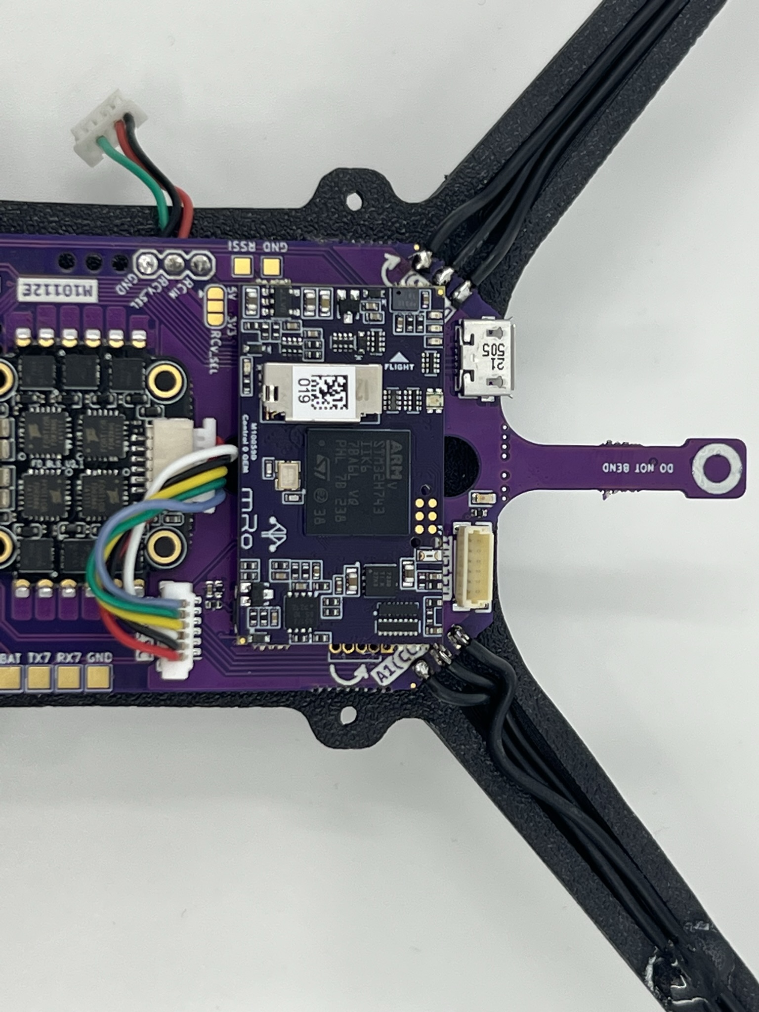
Step 2 - Carrier board subassembly
Carrier board prep
Connect ESC signal cable
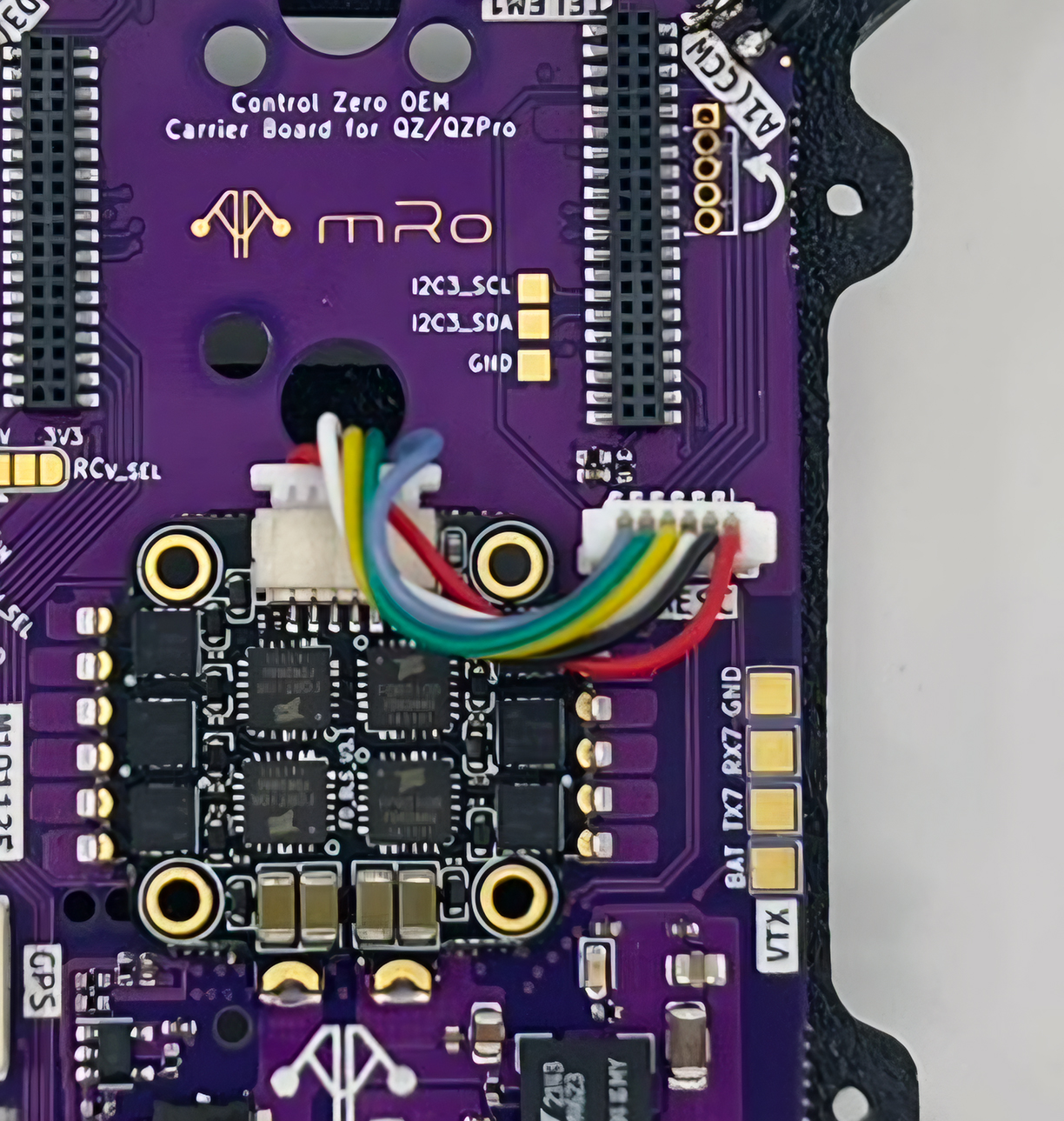
Grab the colorful JST-SH 6 to JST-SH 6 cable and plug it as in the image above.
This cable is generally installed during testing, so this step may not be necessary.
Remove ToF sensor protective cover
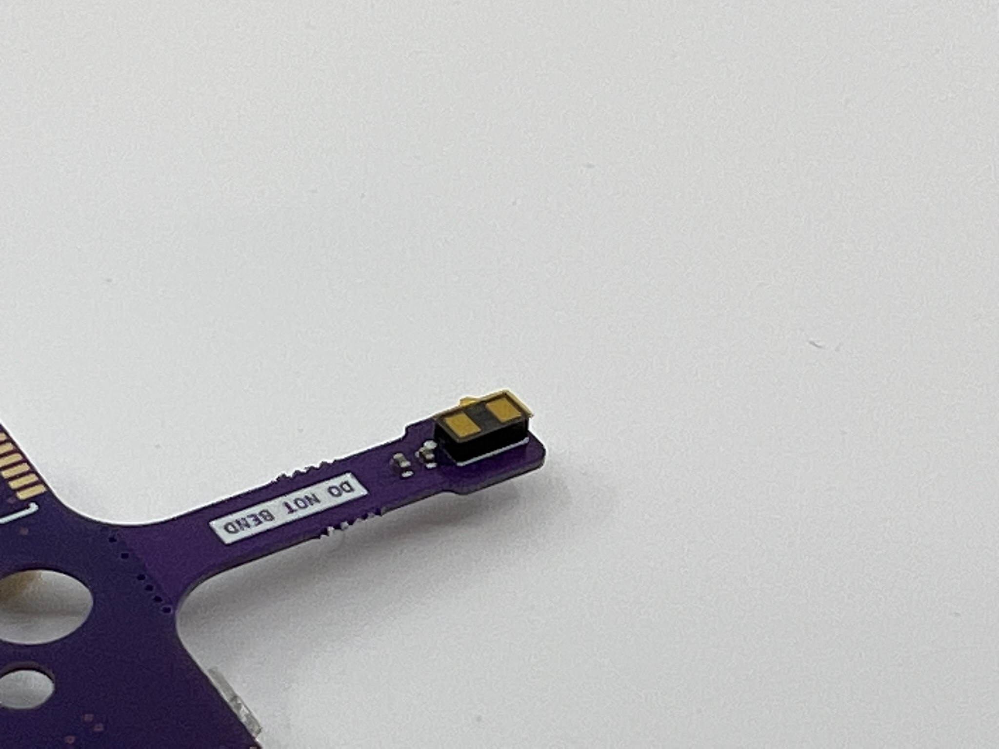
Carefully remove the yellow tape with the plastic tweezers or with your fingers.
Vibration dampers
Cut the provided vibration dampening material by half so you end up with 4 small pieces, to do so you may use a hobby knife or scissors.
Remove the plastic cover on one square and place a small drop of CA glue in the center of any square on the carrier board's back side. Press the square firmly for 10 seconds or until the square no longer slides on the surface.
Repeat for the rest of the corners.
Secure in place
Place the carrier board on its back and remove the remaining damping material adhesive cover.
Add a CA drop on top of each dampening square.
Mount the carrier board onto the frame using the tabs and the side holes to align the carrier assembly. You won't see the tabs in the GIF below, but we changed the steps order so the alignment is easier.
Press firmly for 30 seconds or until CA has tacked.
Remove break away tabs
To remove the tabs you may use any tweezers or bare fingers. Apply a torque or twisting force carefully along the axis of the dotted line, otherwise you may damage the internal layer stackup of the board.
Step 3 - Soldering
Battery connector
Solder the BT2.0 pigtail onto the battery terminals of the M10112 carrier board. The red wire should match the '+' sign in the board.
Motors
Cut the motor cable in order to reach the carrier board's motor pads, our small trick to get the wire length correct consists in pulling the wires above the carrier and cut arpund 5-6mm from the edge of the board. Then strip 3-4mm and pre-tin the ends.
Don't worry for the motor directions at this point, we will verify that using software at a later time. However if you pay attention to detail, you may skip a step later if you solder the front right [A] and rear left [C] motor wires straight (as-is) and swapping any two out of the three wires for the front left [D] and rear right [B] motors. Note: Letters in brackets refer to the corresponding motor as labeled in the carrier board pads.
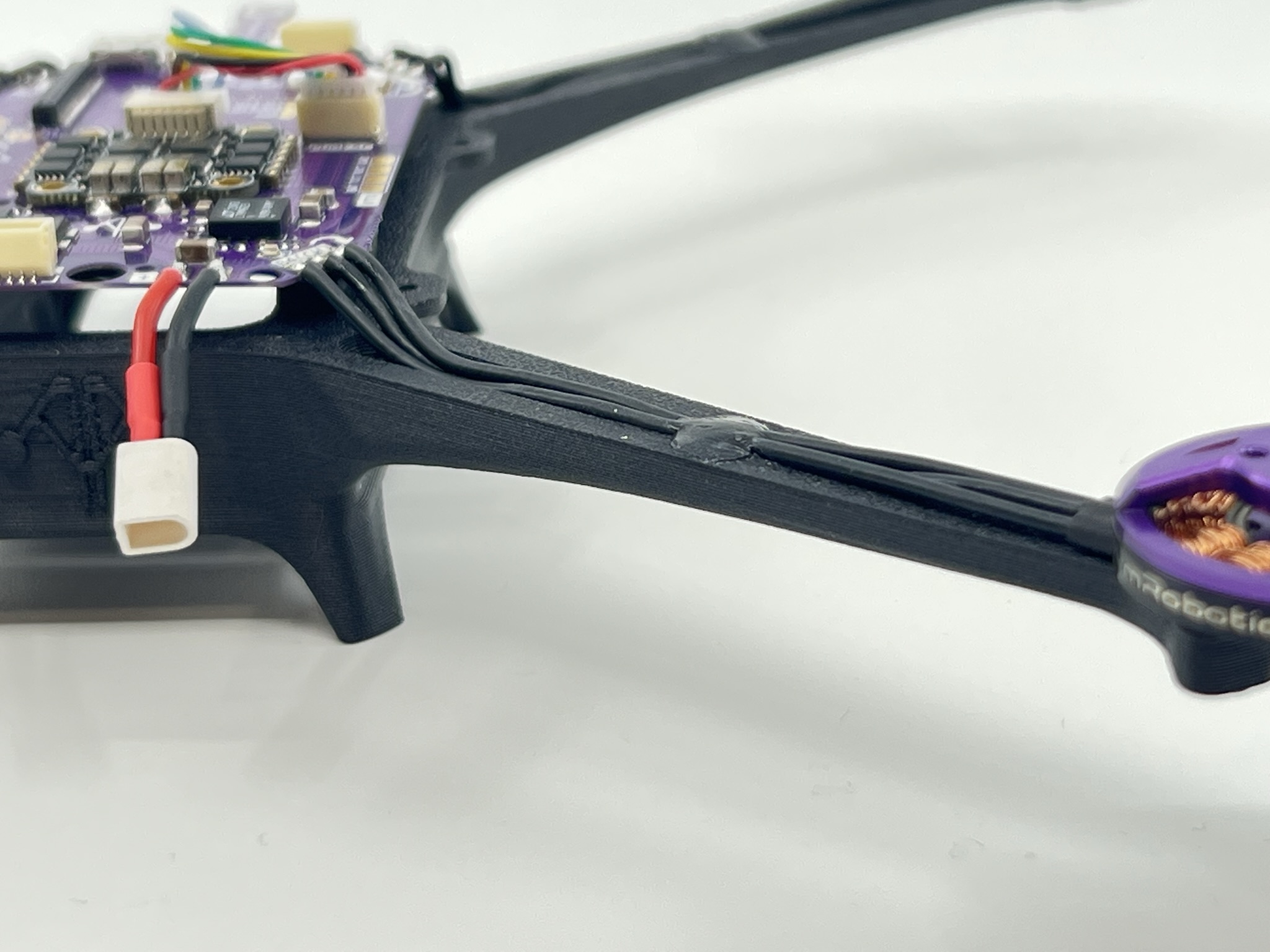
Motor cable management
This is a recommended step which may be completed with a couple of techniques. In previous versions of this guide we recommended using SuperX glue, however the CA method is faster and cheaper. However using a zip tie, hot glue or similar materials is enough. The goal is to mitigate the vibrations from the cables freely moving under the prop wash and prevent prop strikes.
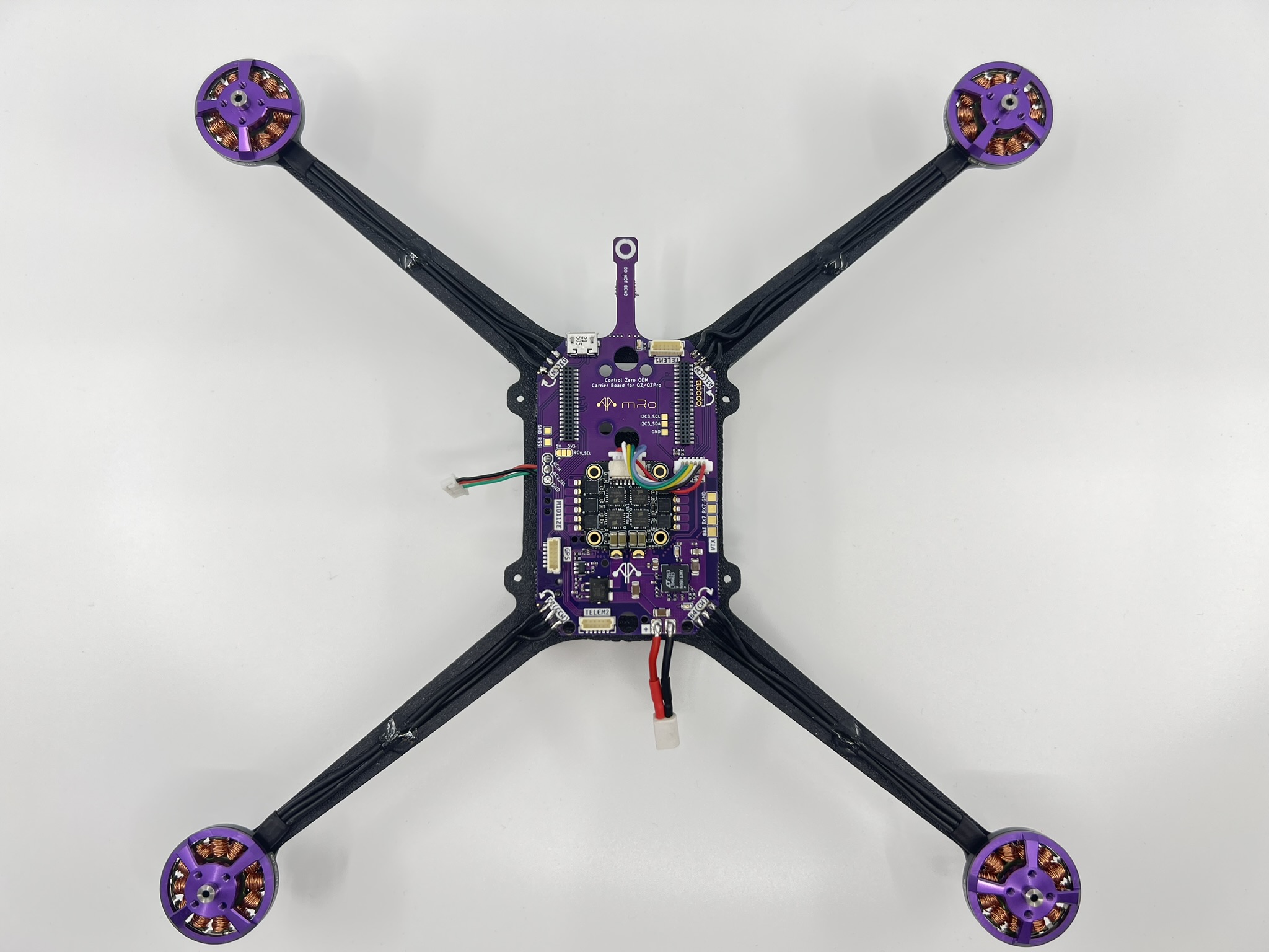
Once you have all the motors soldered, gently pull the cables from the motor towards the center of the frame and apply a generous drop of CA glue at two thirds of the arm's length, making sure it covers the cables. Then apply CA accelerator and wait for it to tack.
Check the following pictures for details.
Step 4 - RF subassembly
You may put the frame assembly on the side for the next couple of steps.
DualBand Telemetry radio
We will start this section by opening the bag that contains the Dual Band telemetry radio. Please handle with care and take ESD protection measures, be particularly rigurous on this if you live in a very dry area.
Allocate the GPS Riser and grab the two 2-56x⅛" nylon hex screws to attach the M10114 Dual Band telemetry radio board to the plastic riser as pictured below.
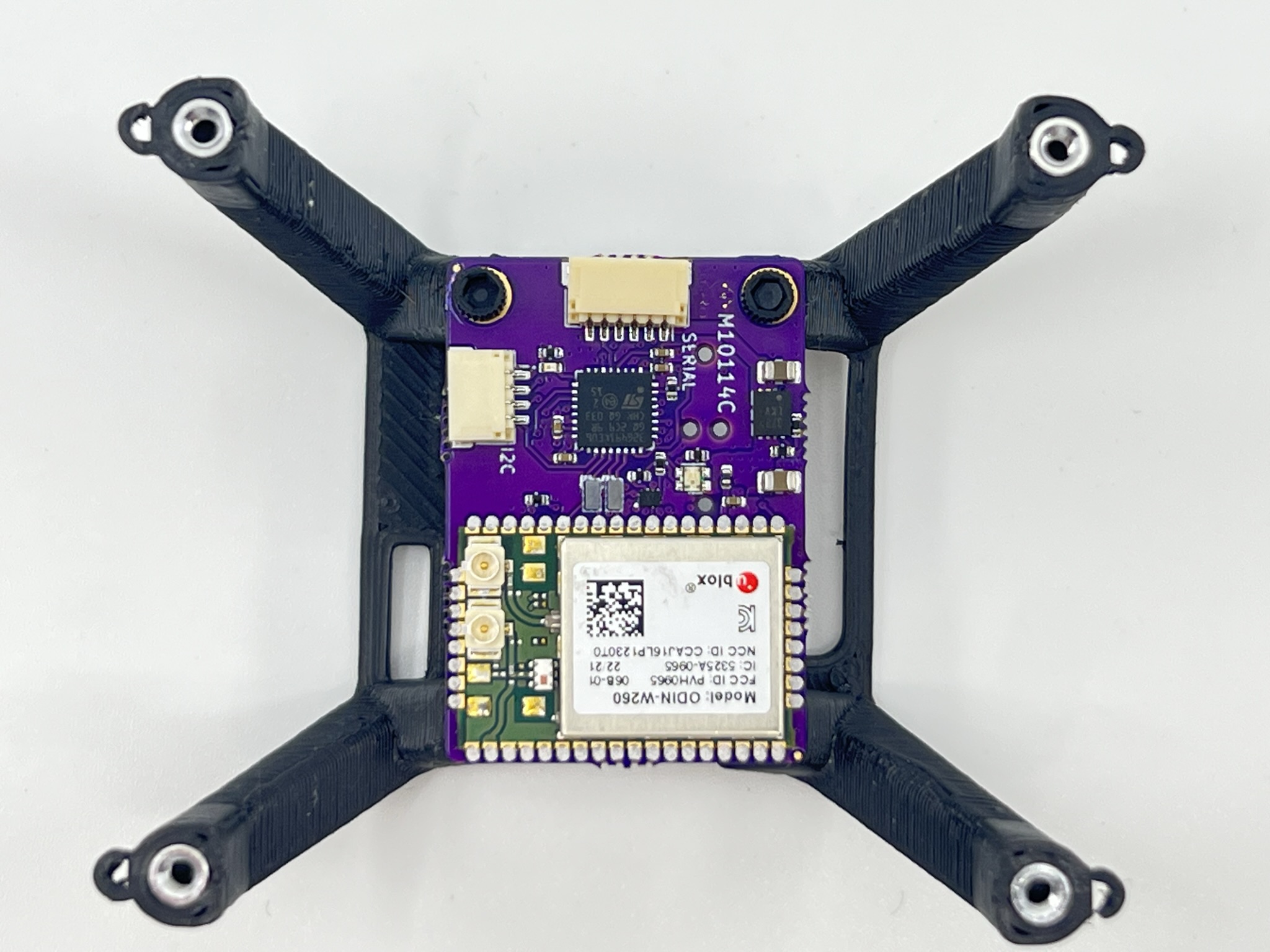
If you are not using the Wifi telemetry radio, you may place any other type of telemetry radio, always taking into account the interference this may cause to the GPS receiver.
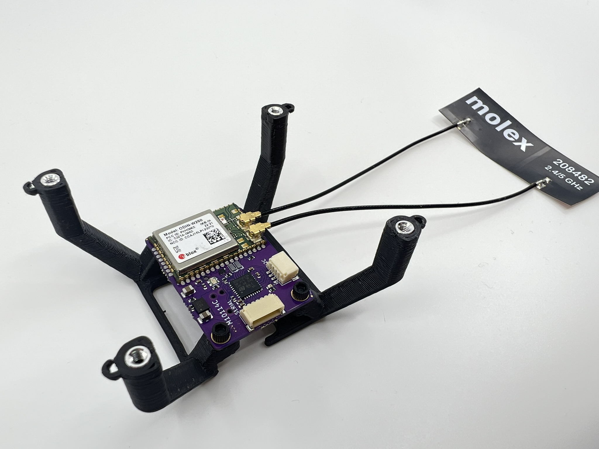
Connect each of the DualBand telemetry radio antenna cables to a u.Fl connector on the wifi module.
GPS Receiver
Place a small 9x9mm double sided tape square and place the GPS on top. We recommend to put smaller squares to increase the contact area, however we have found that the small square is enough.
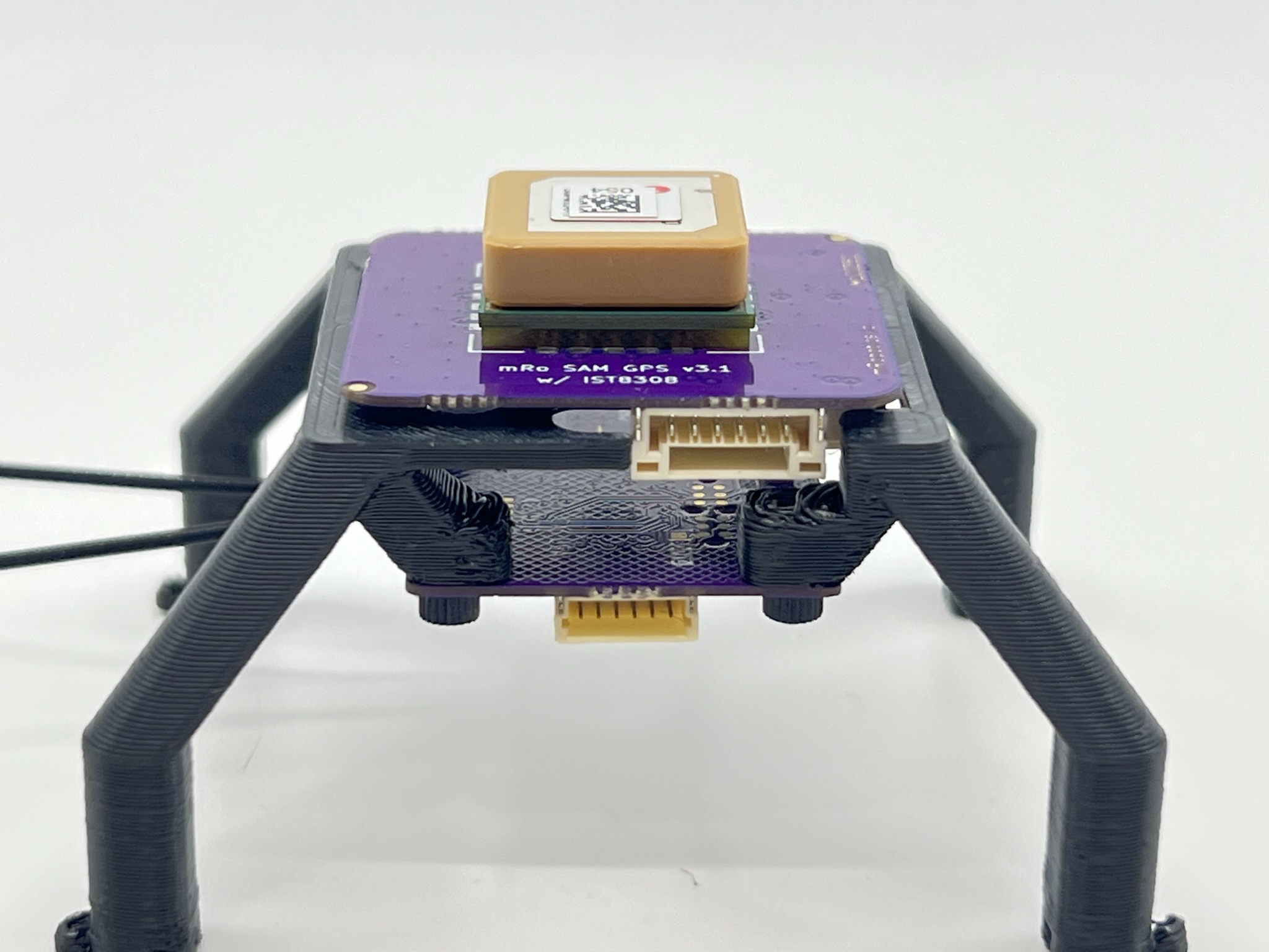
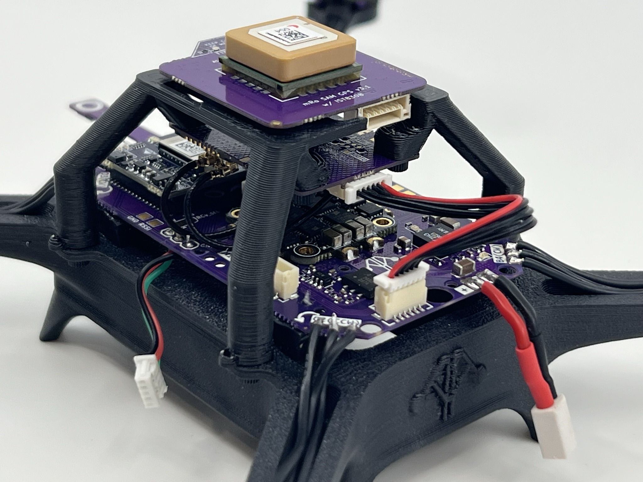
Install autopilot board in place
Remove the Control Zero H7 OEM autopilot from its anti-static packaging taking the same precautions as in the previous step.
Place it with the arrow pointing to the left side of the carrier board, the ToF sensor protrusion is the front direction. There is only one way to couple the FC board to the carrier, since the front header has 36 pins and the rear header has 40 pins.
If for any reasUon you need to remove the Control Zero board, you may do so with the included plastic tweezers, using them as a lever to gently separate each connector 1-2mm at a time.
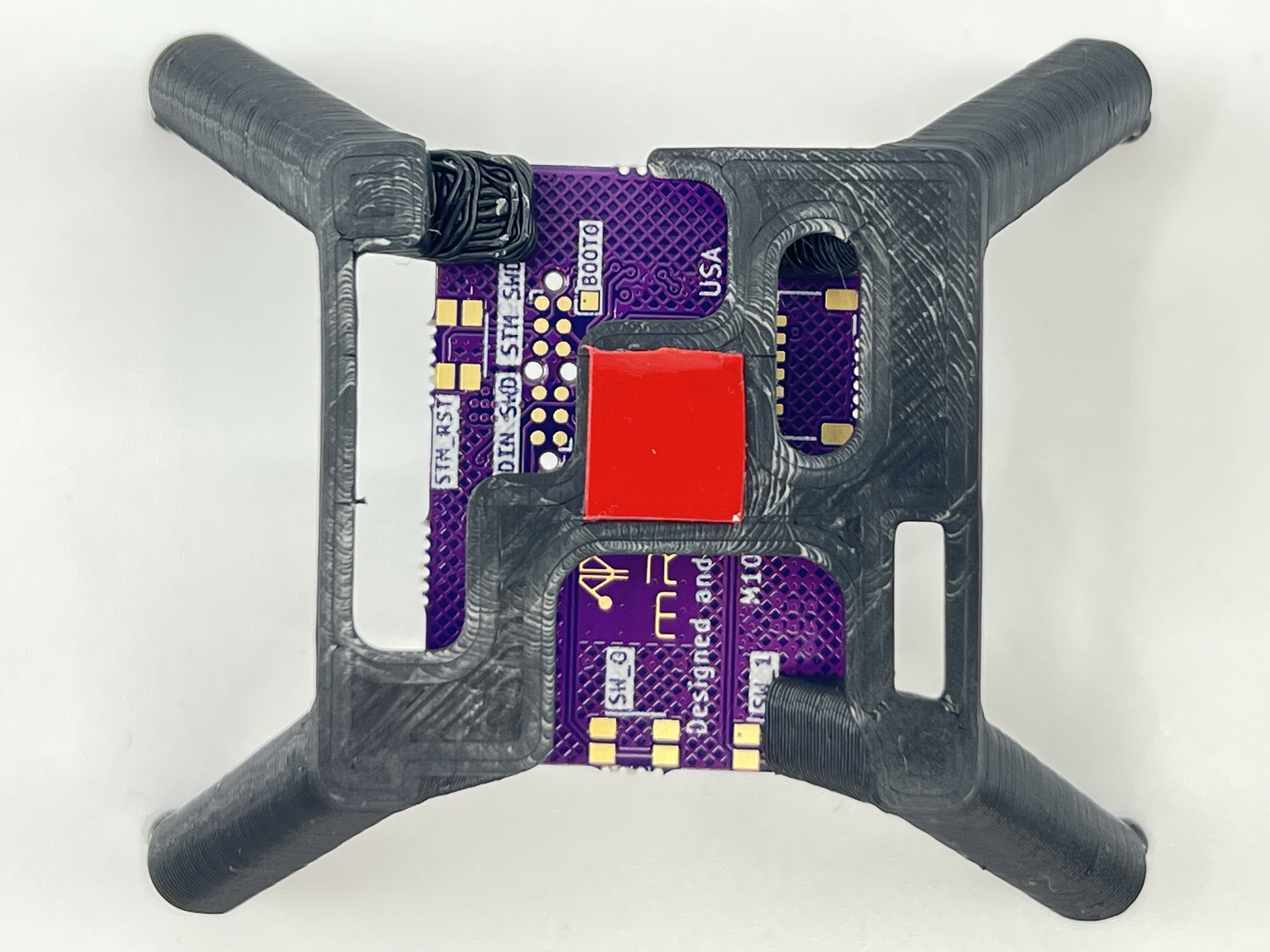
Secure RF subassembly to frame
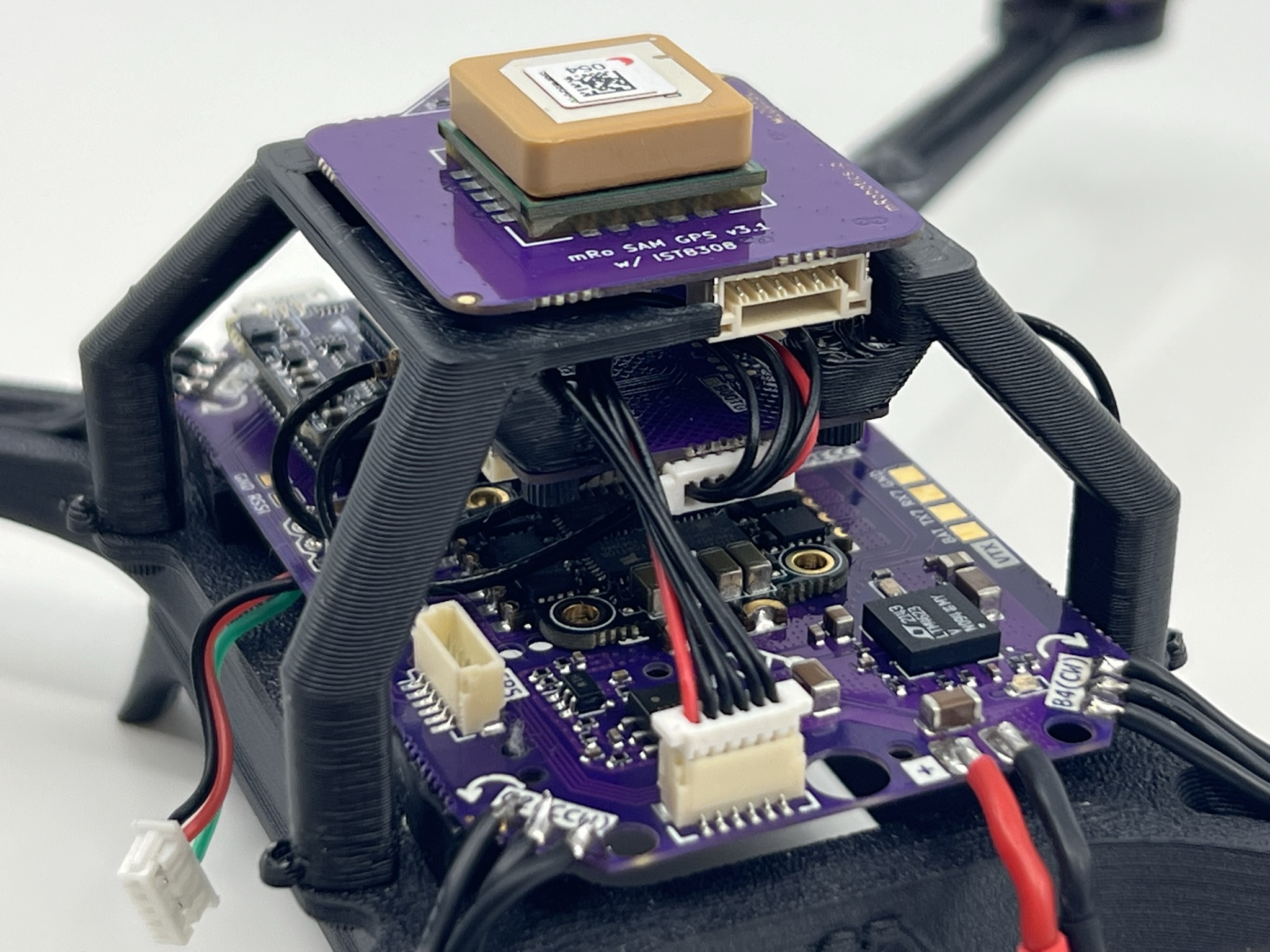
Gently bend the antenna cables 180 degrees so you are able to place it on the right side of the frame. We suggest securing the GPS riser in place before glueing the antenna. To do so, use 4x 2-56x3/16" nylon hex screws.
See picture below for reference. Use CA glue to strengthen the bond as needed.
Cable management
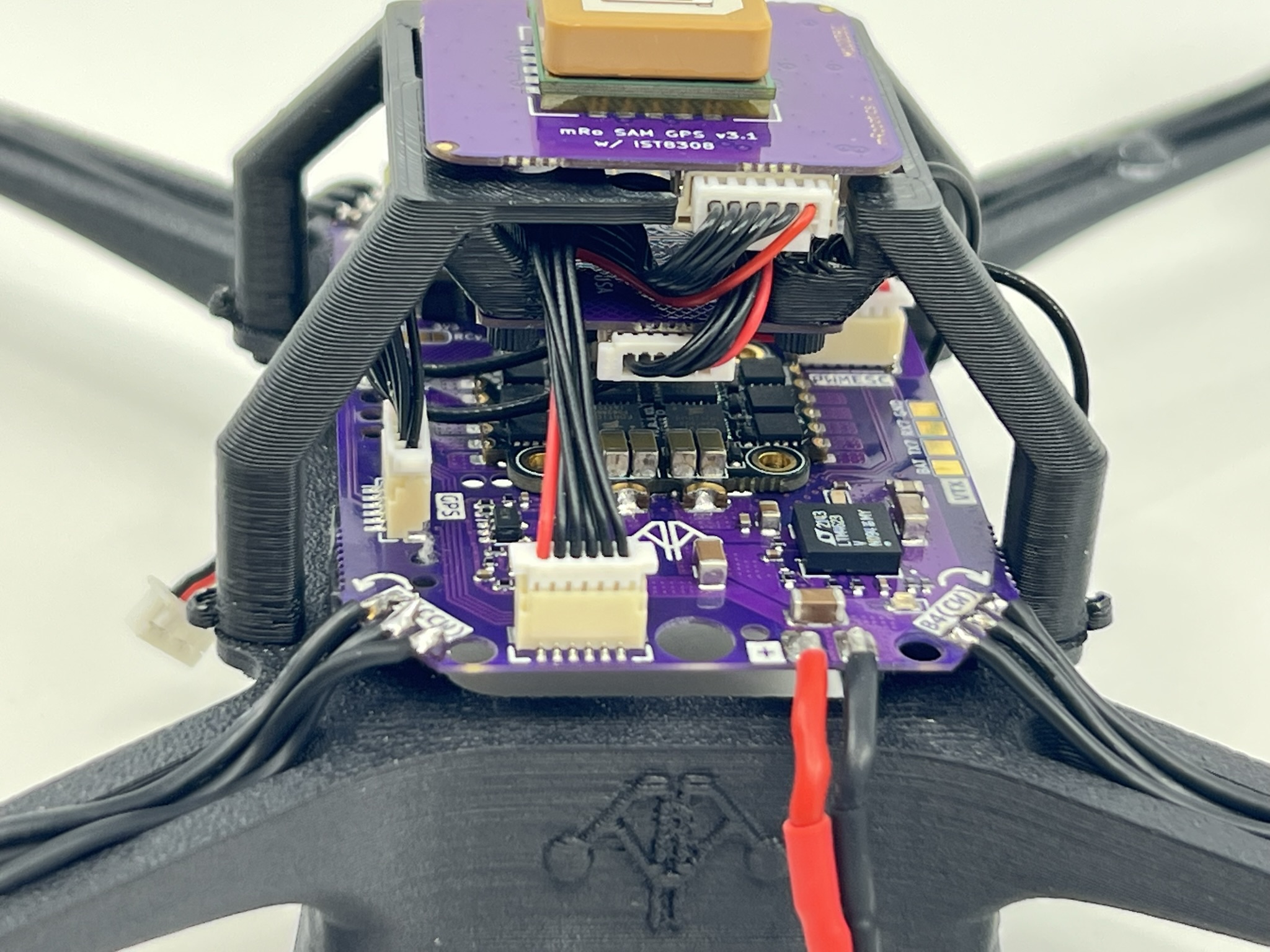
Take one MRC-0292 JST-SH 6-pin to JST-SH 6-pin cable and connect it to the SERIAL labeled connector of the M10114 board (telemetry), then connect it to the TELEM2 port of M10112 carrier board. Check the previous picture for reference.
You may push the extra cable between both boards, making sure not to bend them aggressively.
Then take one MRC-0243 JST-SH 6-pin to JST-GH 6-pin cable, connect the GH end to the GPS Receiver board and rout it through TELEM2 and between GPS and telemetry radio cable, then pull connector from the left side to connect it in the GPS labeled connector on the carrier.
Radio RX wire prep
NOTE: We cannot guarantee the firmware version that ExpressLRS or our distributors ship the receivers with. We recognize this situation might not be ideal for ease of use and are actively working on solutions.
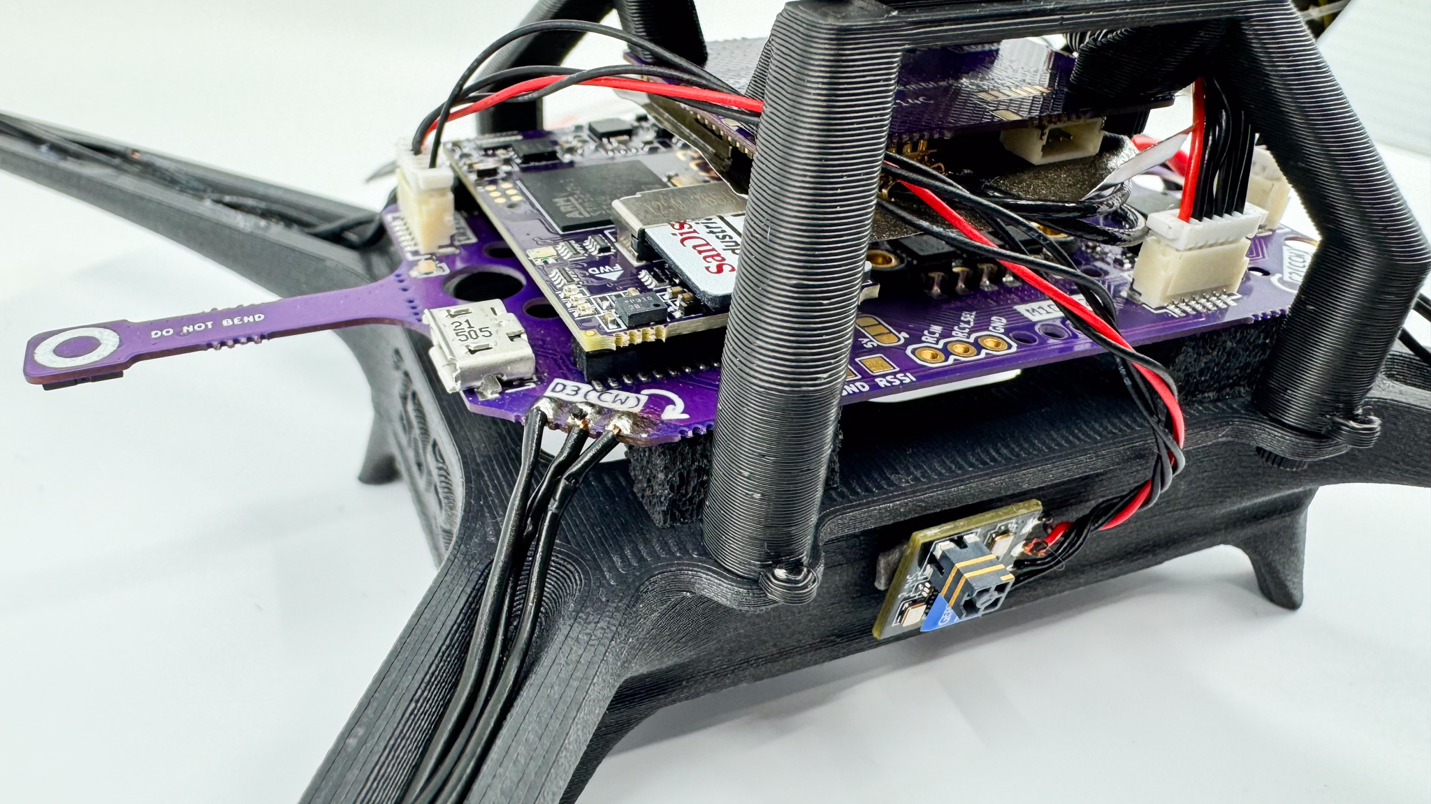
We decided to go with the ExpressLRS receivers due to their compact size and performance. Depending on your specific needs, you might choose to place the receiver in various locations on your drone. This guide will focus on a common setup where the receiver is mounted on the side of the frame.
For starters, once you have the ExpressLRS receiver, take the receiver and the 6-pin JST-SH cable and identify the required connections you'll need. Use the pinout diagram of the ELRS receiver below to properly identify power (5V), ground (GND), and signal (TX and RX for telemetry).
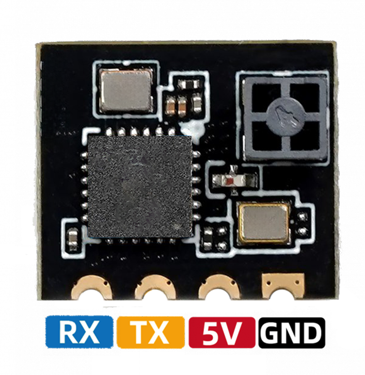
Trim the JST-SH 6 cable to about 40mm or about an inch and a half. If you require to place your receiver elsewhere feel free to do so and cut the cable to your desired length.
Then strip 1mm of silicone-coating from the ends of the 4 cables that you trimmed, and pre-tin them to make the soldering process much easier.
Then remove the 2 unused cables from the JST housing.
Make sure to follow the telemetry port pinout chart provided below while soldering the cables to the ELRS pads. Keep in mind that the ELRS receiver does not support hardware flow control, so we will leave the CTS and RTS cables floating.
Next, solder the pigtails to the ExpressLRS receiver as described below.
| Pin | Color | Signal | TTL/Voltage Level |
|---|---|---|---|
| 1 | Red | VCC | 5V |
| 2 | Black | TX | 3V3 |
| 3 | Black | RX | 3V3 |
| 4 | Black | CTS | 3V3 |
| 5 | Black | RTS | 3V3 |
| 6 | Black | GND | N/A |
Now after you finish soldering the JST cables to the ELRS receiver pads, cut a piece of double sided tape and put it on the side of the board opposite to the ceramic antenna side.
ExpressLRS Configuration:
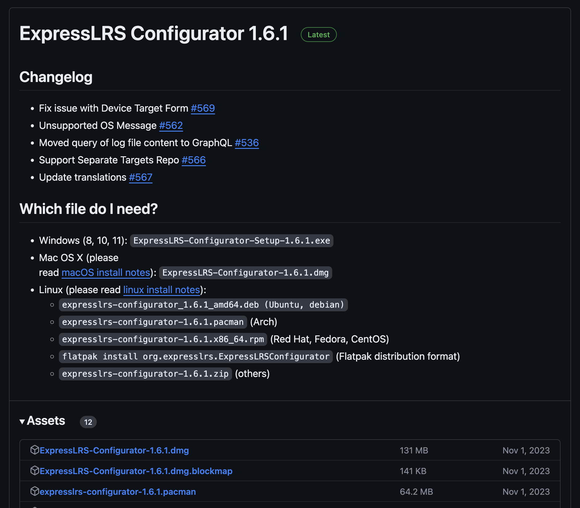
Download and install ExpressLRS Configurator. The configurator is used to compile and flash firmware to the ExpressLRS module and the ExpressLRS receiver. Click here to follow the steps to download and install the configurator.
Download the latest ExpressLRS Configurator, looks like the current version is 1.6.1 and find the version that also matches your operating system.
This guide will be using the Radiomaster Zorro with Internal ExpressLRS TX to bind to the ExpressLRS receiver. But you can use any radio with an internal or external ExpressLRS transmitter.
To bind the radio to the receiver, we first need to flash our module and get the ExpressLRS Lua Script onto our radio.
A Lua Script is a program that runs on the radio and is used to configure the ExpressLRS system
Radios with ExpressLRS built in come pre-shipped with the ExpressLRS Lua Script installed, but if you want to check to see if you have the latest version in your radio press the SYS key, then go to SD Card, scroll down to [SCRIPTS], then scroll down to [TOOLS], click on it and you should see elrsV3.lua as one of the options. (Keep in mind that elrsV3.lua is the latest version when creating this guide)
If you have an older version of Lua Script, you’ll need the latest version, so connect your radio via usb to your computer. Once you connect your radio, a menu will pop up on your screen. Click on "USB Storage (SD)" option.
Once your radio is connected, go to the ExpressLRS Configurator that you downloaded earlier.
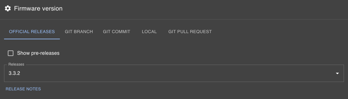
We're going to choose the version of firmware flashing and we'll just pick the latest release version.
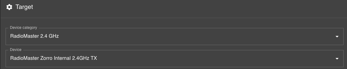
Scroll down to "Target," click on "Device Category," and select your transmitter module type. Then, under "Device," choose the specific transmitter module.
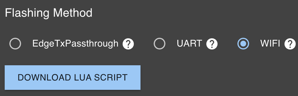
Now select the "WIFI" option under the Flashing Method and click on the blue box to download the Lua Script.
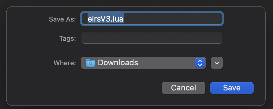
Save the new file.
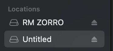
With the downloaded file, navigate to the "Untitled" drive. Look for the SD Card contents within the drive, go to SCRIPTS -> TOOLS and save the "elrsV3.lua" file in the TOOLS folder.
After transferring the downloaded Lua Script file to your radio's SD Card, unplug your radio to configure its settings.
Press the "MDL" key on your radio and navigate to the "MODEL" setup menu. For an internal ExpressLRS module, set the internal module to "CRSF." For an external module, turn the internal RF off and set the external RF to "CRSF."
Next thing we need to do is exit "MODEL" settings, press "SYS," and navigate to the "TOOLS" page. Click on "ExpressLRS" and adjust the ExpressLRS Lua Script settings as follows:
-
Set Packet Rate to 500Hz.
-
Change Teleme Ratio to Std (1:128).
-
Switch Mode to Wide.
All other settings can be configured according to your preference.
Bakc in the ExpressLRS Configurator, select your regulatory domain according to your location: - For the EU: Choose “REGULATORY_DOMAIN_EU_CE_2400” - For any other location: Select “REGULATORY_DOMAIN_ISM_2400”

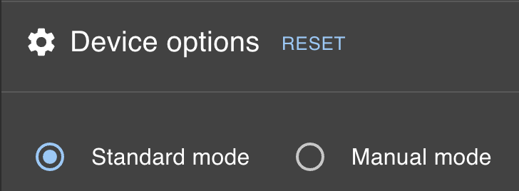
Under "Device options" make sure the "Standard mode" is selected.
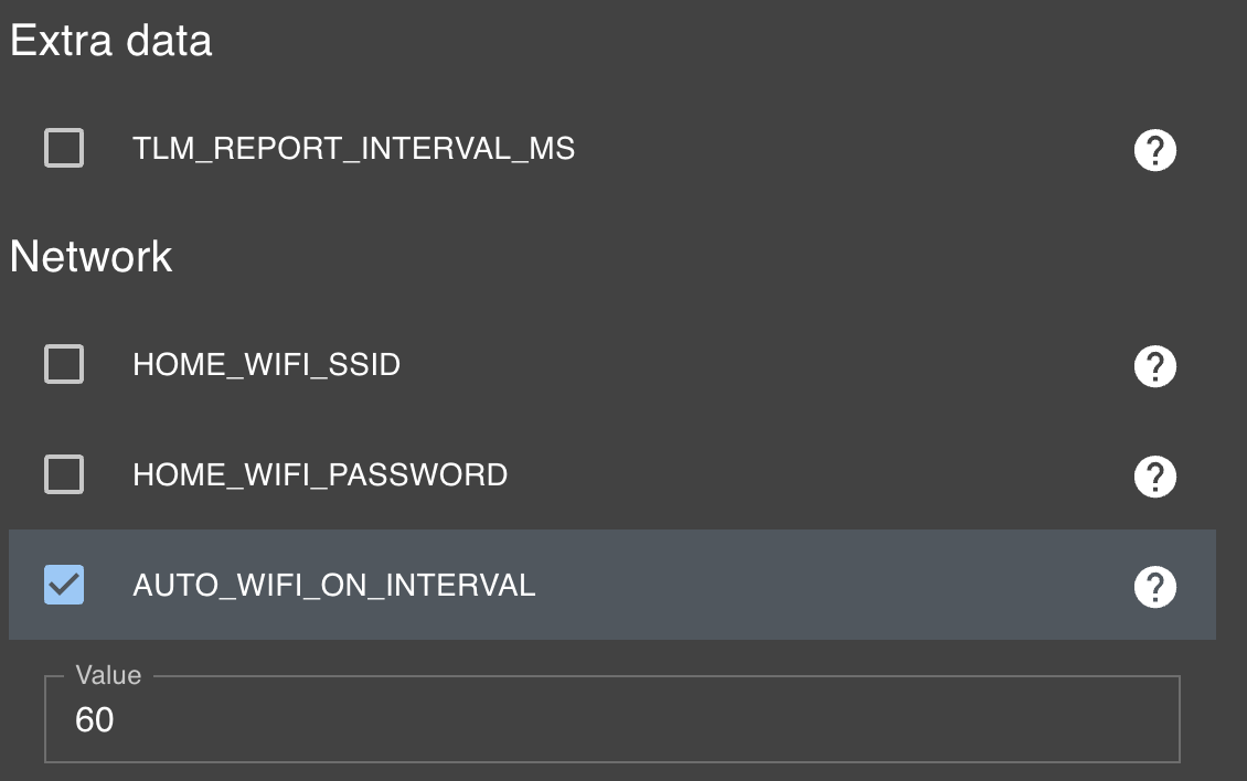
Leave the "Extra data" option as is. Under "Network," click on "AUTO_WIFI_ON_INTERVAL", and set the Value to 60 if it isn’t already.
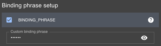
Navigate to and click on BINDING_PHRASE, then enter your phrase in the "Custom binding phrase" box that appears.
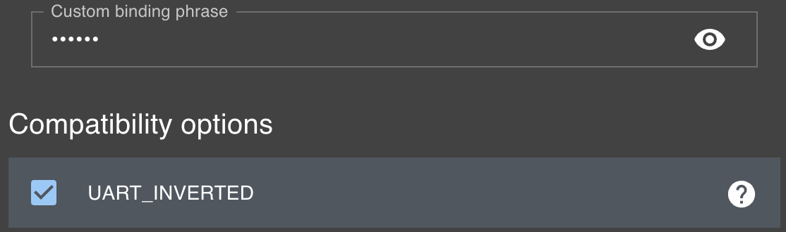
Select UART_INVERTED under compatibility options.
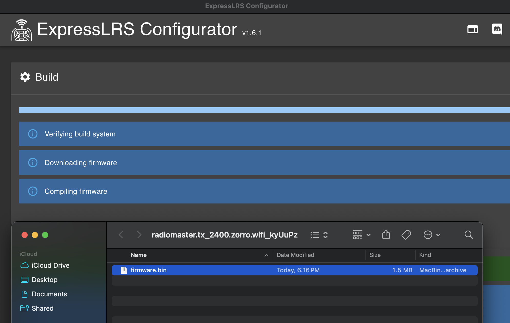
After all the parameters are set in the ExpressLRS Configurator, click “Build” at the bottom of the configurator. If it’s your first time, the loading process might take up to 10 minutes.
After the "Build" process completes, you'll receive a file necessary for flashing your module via WiFi. Save it in an easily accessible location.
Return to your radio, press the "SYS" key and run the ExpressLRS Lua Script once more. Scroll down to "Wi-Fi Connectivity" and select "Enable Wi-Fi".
While the Wi-Fi is running,look for "ExpressLRS TX" in the visible networks on your computer. - The network password is: expresslrs
After connecting to the "ExpressLRS TX" Wi-Fi network, open up your browser and type the IP address 10.0.0.1
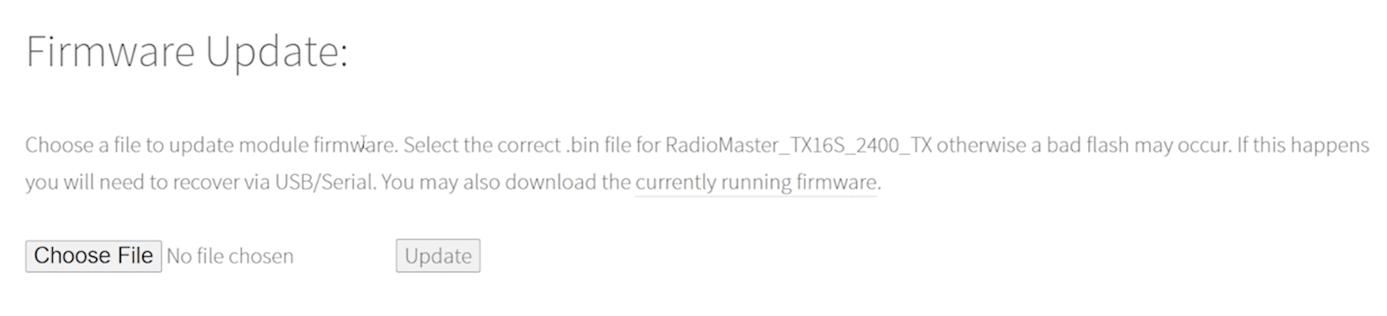
Once you're on the "ExpressLRS update page," scroll down to find "Firmware Update." Click on "Choose File," select the .bin file created during the Build process, and then click "Update."
After updating your radio's firmware, you'll now flash the receiver using Wi-Fi. Power up your quadcopter; the receiver's blue LEDs should start blinking. Wait for 20-30 seconds until the LEDs blink rapidly, showing that it's in Wi-Fi mode.
Then, do the same process you did with the radio, find and connect to the "ExpressLRS RX" Wi-Fi network on your device and connect using the password: expresslrs
Go back into the ExpressLRS Configurator and keep the same settings you set prior for your transmitter, and select "Build".
After the "Build" process completes, you'll receive a file necessary for flashing your ExpressLRS receiver via Wi-Fi. Save it in an easily accessible location.
Type the IP address, 10.0.0.1, into your browser.
Just like you did with the transmitter, select "Choose File" under "Firmware Update:" and select the RX file. Then click "Update" to flash your receiver.
Finally, connect your quadcopter to Mission Planner to set up the needed parameters so that the Expresslrs receiver works properly.
In Mission Planner go to CONFIG ---> Full Parameter List. Set these paramters:
Mission Planner Parameters:
| Name | Value |
|---|---|
| SERIAL1_BAUD | 115200 |
| SERIAL1_PROTOCOL | 23 |
| RC_OPTIONS | 10752 |
| RC_PROTOCOLS | 521 |
| SERVO_BLH_AUTO | Enable |
| SERVO_BLH_MASK | 15 |
| SERVO_BLH_OTYPE | 5 |
| SERVO_DSHOT_ESC | 2 |
Then select "Write Params"
Go back to "DATA" select "Actions" select "Preflight_Reboot_Shutdown" then select "Do Action"
Step 5 - Autopilot Configuration
You will have to evaluate which flight stack you will be running in your QZKit. The 3DR Control Zero H7 OEM is supported by Ardupilot and PX4, both broadly capable and stable open source projects. We provide instructions for both platforms with a minimum set of directions and parameter files.
Ardupilot
The 3DR Control Zero H7 OEM board comes with ArduPilot flashed out of the box. Connect your carrier board to any computer running Mission Planner (MP) software and update to the latest stable version, AC4.5.7 at the time of writing. Please follow this guide if you need further details.
Parameter list
After updating the firmware, connect via MAVLink using 115200 as baud rate value, this setting is located on the top right corner of any screen in MP software, then click on the Settings tab.
Click the Load Parameters button and select the downloaded .param file. Click to download
Allow once you press OK button (reboot prompt) wait until the beep Parameters succesfully saved Should reconnect auto, if not just press disconnect and Connect .
PX4
Even if our board ship with Ardupilot out of the box it doesn't mean using PX4 is an advanced or complicated task. Fortunately both projects offer a common bootloader behavior which will be recognized by either software. Please do not attempt to change the bootloader. The steps to load PX4 onto the Control Zero H7 OEM board are the following:
-
Open QGroundControl (QGC) software. Leave the carrier board unconnected.
-
Click on the upper left corner (QGC logo), then click the Vehicle Setup button.
-
You should see that there are only two tabs on the left pane: Summary and Firmware. No hardware should be connected at this point!
-
Click on the Firmware button and proceed to connect your board.
-
Select the branch or firmware flavor you need to upload. Note that you can choose either PX4 Pro or Ardupilot software from the menu. If you check the Advanced settings box you may select to upload any other binary. In this case select PX4 Pro to the latest stable version
 .
. -
Wait until the writing and verification process ends. The board will reboot and it will start beeping afterwards.
-
You may now connect to it as usual from the QGC communications pane.
Parameters file
Coming soon!
Wireless telemetry link
Once you have performed the minimum configuration you may disconnect the USB cable and proceed to use the telemetry radio for the rest of the configuration steps. With your QZ powered from the battery, wait for the Status LED on the 3DR DualBand Wi-Fi Telemetry Radio to turn solid green, a Wi-Fi network will be created automatically.
Then connect your device to the mRo_wifi network using controlZero as password.
Use the following configuration settings to establish communication with your GCS software:
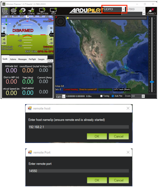
Mission Planner
Select UDPCl as the connection type. Enter 192.168.2.1 when prompted for the hostname, and 14550 as the remote port.
QGroundControl
Click on the QGC Logo on left top corner > Applications Settings > Comm Links > Add > Insert the following parameters:
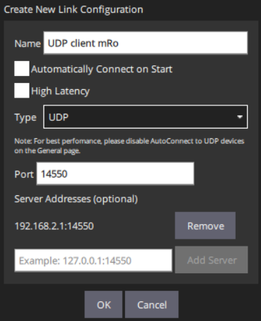
Select the newly created connection and click connect below.
Sensor calibration, RC setup and motor direction check
Regardless of the flight stack you are running, you must perform these calibration steps to ensure a completely configured platform.
For Ardupilot:
For PX4:
Final assembly steps
Motor Direction Test
Warning
Ensure there are no propellers on the motors at this point.
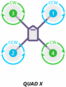
Motor directions should match the following diagram:
To do this test on Mission Planner go to: Setup > Optional Hardware > Motor Test
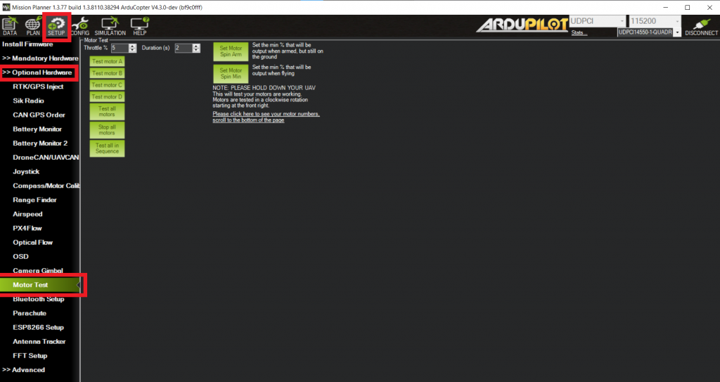
Click on each motor to verify motor spin direction and motor order. If the motor direction is wrong, you can reverse the movement by swapping two of the three ESC to motor power leads.
For more info please visit - Connect ESCs and Motors — Copter documentation.
On QGroundControl, go to Vehicle Setup > Actuators:
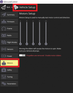
Please check PX4/QGC wiki for further information, note that since v1.13 the Control Allocation feature is available: - Actuator Configuration and Testing | PX4 User Guide - Use the manual output sliders to verify correct order and spin direction.
For more information about motor directions, you can follow the next link:
Props & motors subassembly
Before installing the propellers, we strongly advise to balance them statically. Even if manufacturers label the props as pre-balanced you should double and triple check this fact experimentally using a propeller balancer tool.
Install propellers
Use 2 included M2x5mm screws per motor to secure the propeller in place. Loctite is allowed for extra security. Ensure the propellers are mounted correctly according to the previous section links.
If you have issues identifying the CW vs CCW please see Recognizing clockwise and counterclockwise propellers.
Dynamic balancing
Warning
This step involves running the motors with the propellers on the bench, if you do not feel comfortable doing so there are alternative ways of achieveing the similar results. We highly recommend doing this step if you want the best performance from your Quad Zero Kit as motors will run quieter and cooler and the estimators will be much happier if the autopilot is not vibrating violently from a poorly balanced motor-prop assembly. We would like to do this step for you to guarantee the best experience out of the box, however it is time-consuming and it would require a strict labeling for positioning the propellers on the motors thus bringing an increase in lead times and price.
Use the steps described above for verifying the motor direction to actuate each motor individually. We suggest to run it to 30% and 60% approximately, while holding the arm carefully with your fingers. Excessive vibration will be evident and counterweights should be placed until the results satisfy yourself.
Fly responsibly, safely and securely.
Happy flying!