Septentrio mosaic-X5 RTK L1/L2/E5 GPS
The 3DR mosaic-X5 L1/L2/E5 RTK CAN GPS is the latest addition to our high-performance GPS family of products. Introducing Septentrio’s staple GNSS receiver, the mosaic-X5 as the latest standard for resilient and high performance, low latency applications (100Hz), it offers a wide feature set that allows easy configuration and spectrum analysis as well as logging and other post-processing features relevant for earth sciences. This no-compromise board integrates CAN connectivity, the RM3100 magnetometer, a DPS310 barometer and a WiFi module for on the go access to the mosaic-X5’s web server functionality; everything under a plastic enclosure. Our all-in-one antenna + receiver + CAN node uses less space and weight than most active antenna counterparts and eliminates signal loss caused by u.Fl/SMA antenna connectors and long cables.
Purchase The MosaicX5Specifications
Section titled “Specifications”| Specifications | 3DR mosaic-X5 |
|---|---|
| Constellations | GPS (L1/L2/L5), Galileo (E5b), Glonass (L1/L2) |
| Compatibility | Ardupilot (NMEA), PX4 |
| Compass | RM3100 |
| Barometer | DPS310 |
| RTK ready | Yes |
| USB Port | Yes (Type C) |
| CAN ready | Yes |
| SD logging | Yes |
| Minimum and Maximum Operating Temperature | -40 ~ 85 °C |
| LED | ARM: RGB LED, Status: PPS, LOG, PWR, MCU, USR |
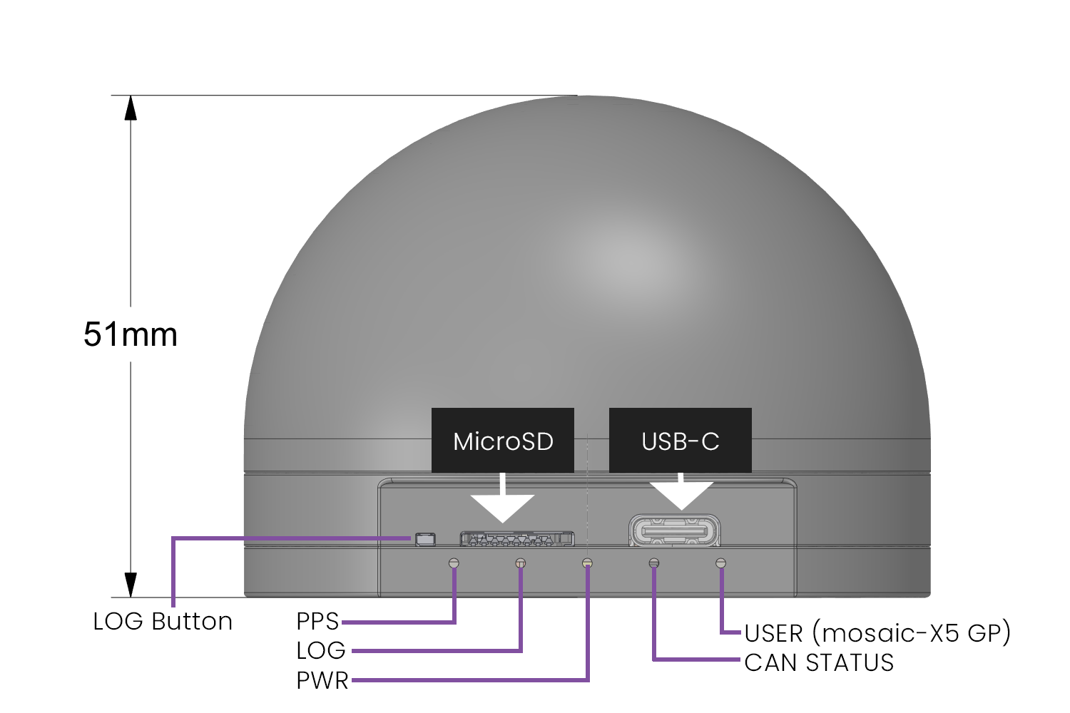
| Dimensions | D2¾ in x 2in (D70mm x 51mm) |
| Weight | 2oz (57g) |
| Mounting Holes | 5xM2 for self-tapping screws on the bottom side |
| Case | Included |
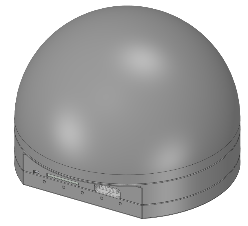
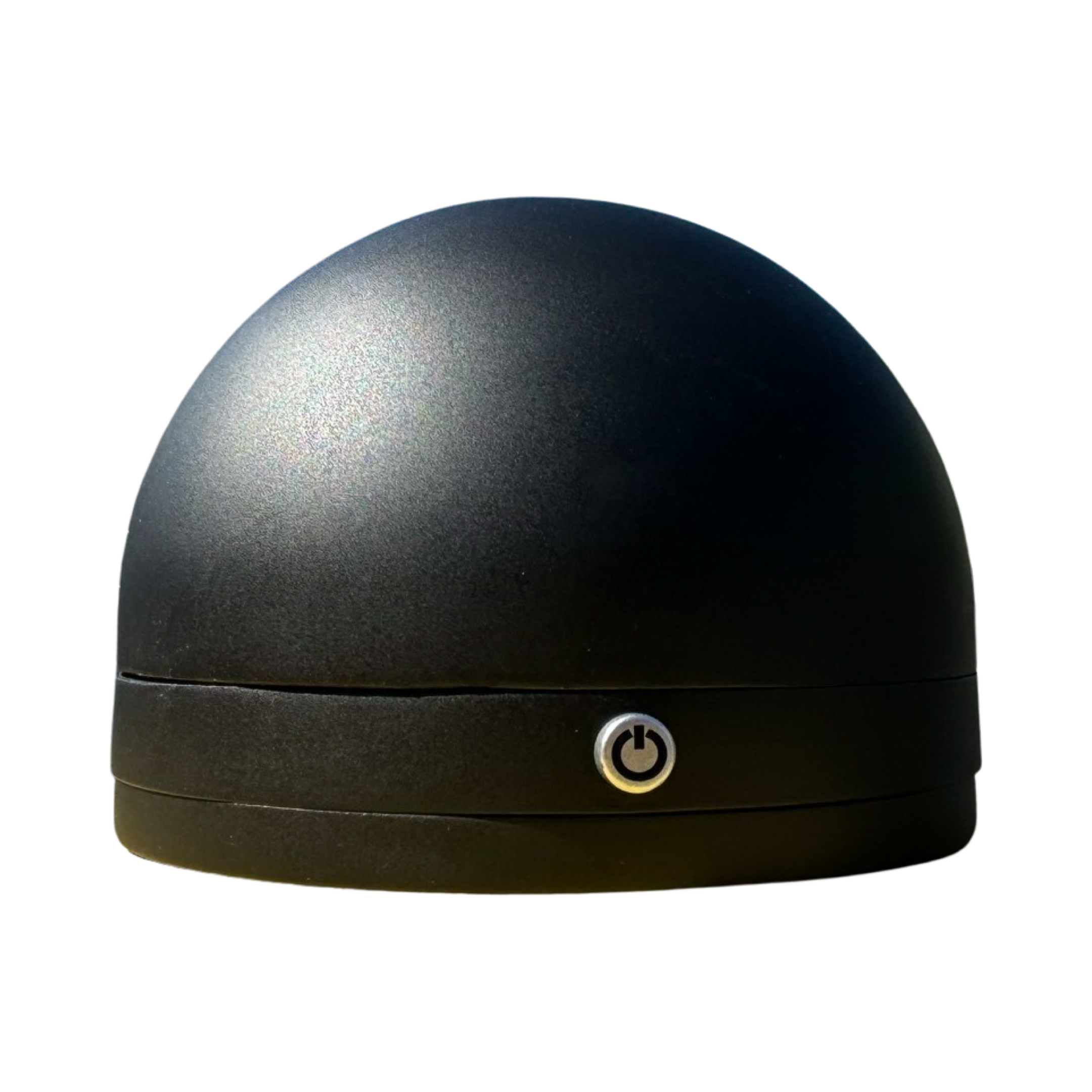
The receiver is implemented in a compact plastic UV-resistant enclosure, with an arming button on the front and a set of debugging and logging connectors in the rear:
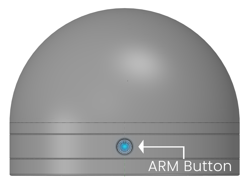
The ARM button has an illumination for status indication:
The rear side of the receiver allows easy access to the USB and microSD card. A set of status indicators could be helpful to diagnose the system.
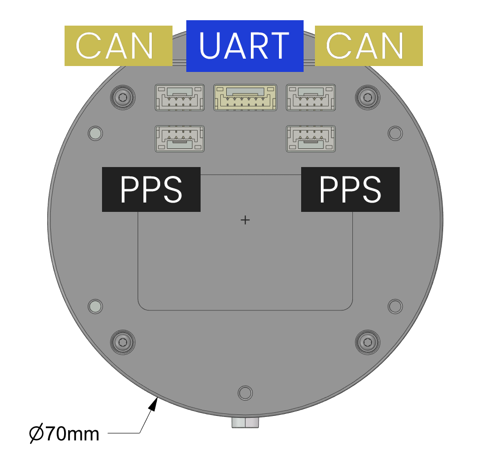
A set of system integration connectors is located on the bottom of the receiver, which includes CAN/UART/CAN connectors in the first row, and two PPS output connectors in the second row:
Firmware
Section titled “Firmware”Pinout
Section titled “Pinout”All ports are JST-GH connectors, with pin 1 being the left when holding the cable tab up.
X5 GPIO 1
Section titled “X5 GPIO 1”| Pin | Signal | TTL/Voltage Level |
|---|---|---|
| 1 | VIOA | 3.3-5V |
| 2 | PPS OUT | VIOA |
| 3 | EventA IN | VIOA |
| 6 | GND | N/A |
X5 GPIO 2
Section titled “X5 GPIO 2”| Pin | Signal | TTL/Voltage Level |
|---|---|---|
| 1 | VIOB | 3.3-5V |
| 2 | PPS OUT | VIOB |
| 3 | EventB IN | VIOB |
| 6 | GND | N/A |
CAN 1/2
Section titled “CAN 1/2”| Pin | Signal | TTL/Voltage Level |
|---|---|---|
| 1 | VDD | 3.3-5V |
| 2 | CANH | N/A |
| 3 | CANL | N/A |
| 6 | GND | N/A |
mosaic-X5 USART2 breakout
| Pin | Signal | TTL/Voltage Level |
|---|---|---|
| 1 | VCC | 5V |
| 2 | RX | 3V3 |
| 3 | TX | 3V3 |
| 4 | RTS | 3V3 |
| 5 | CTS | 3V3 |
| 6 | GND | N/A |
mosaic-X5 USB port.
Wiring
Section titled “Wiring”| Pilot | GNSS |
|---|---|
| VCC | VCC |
| TX | RX |
| RX | TX |
| I2C_SCL | I2C_SCL |
| I2C_SDA | I2C_SDA |
| GND | GND |