Seda ESC 35
Introducing Seda ESC, a BLDC motor drive that brings quality-of-life improvements at an affordable price and is fully NDAA-compliant. Like all of our boards, it is fully assembled and tested in California, USA.
The R0040 is the first board in this product line and is designed for 2–6S lithium battery input at up to 35A continuous current draw, its small form factor is great for small and mid-size multirotor and fixed-wing propulsion systems.
Our new ESC line delivers exceptionally smooth, low-noise output across the full throttle range — quieter cruise and noticeably less vibration coupled into the airframe. The result is cleaner IMU data, steadier hover, and longer flights from the same battery. We achieve this with the latest-generation FETs, the highest-quality passives, and some old-school know-how for spinning metal.
The autopilot drives the board with a single DShot or BDShot signal line. A JST-SUR USB port is provided for firmware updates, bench-side configuration, and command-line control(!). Battery and motor leads are soldered directly to the board to keep the assembly compact and to minimise resistive losses at high current.
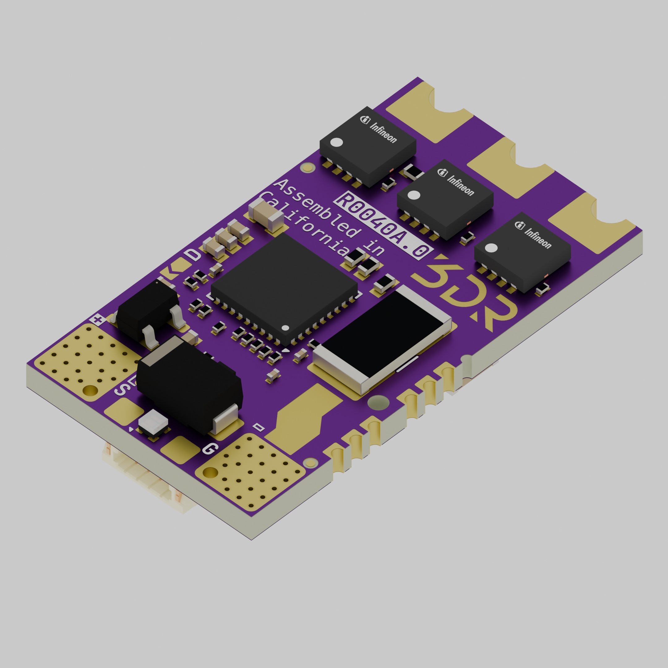
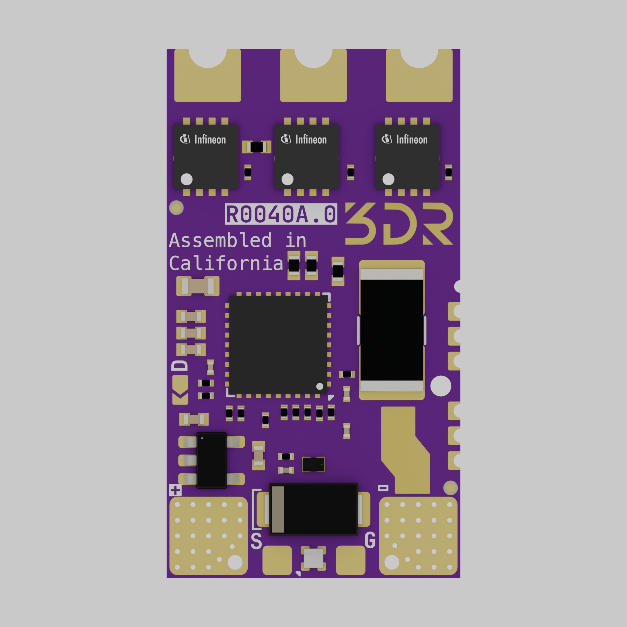
3D View
Section titled “3D View”Specifications
Section titled “Specifications”| System | |
|---|---|
| Topology | 3-phase BLDC inverter |
| Throttle protocol | DShot300, DShot600, BDShot |
| USB | Full-speed (firmware, configuration, command) |
| CoO | USA |
Electrical
Section titled “Electrical”| Electrical Specifications | |
|---|---|
| Input voltage | 6 – 26 VDC (2–6S) |
| Absolute max input | 26 VDC (clamped by input-side TVS) |
| Continuous output current | 35 A |
| Peak output current | 60 A |
| Current sensing shunt | 1 mΩ |
Mechanical
Section titled “Mechanical”| Mechanical Specifications | |
|---|---|
| Board dimensions | 27.0 mm × 15.0 mm |
| Board thickness | 1.6 mm |
| Battery interface | Solder pads (4 mm × 4 mm, double-sided) |
| Motor interface | Solder pads |
| Throttle interface | Solder pads (DShot signal + GND) |
| USB interface | JST-SUR 4-pin, 0.8 mm pitch, horizontal |
Changelog
Section titled “Changelog”- Initial Release
USB (JST-SUR 4-pin, 0.8 mm pitch)
Section titled “USB (JST-SUR 4-pin, 0.8 mm pitch)”| Pin | Signal | Description |
|---|---|---|
| 1 | VBUS | USB +5V (host-supplied, 5 VDC) |
| 2 | D− | USB D- |
| 3 | D+ | USB D+ |
| 4 | GND | Ground |
Wiring
Section titled “Wiring”Solder the battery pack to VBAT and GND. Solder the three motor leads to U / V / W; phase order is not critical — swap any two leads to reverse rotation. The autopilot connects to the DShot signal pad with a ground return. The USB port is used only for firmware updates and bench-side configuration, and is not required for flight.
An input electrolytic capacitor is recommended (typically ≥ 47 µF, ≥ 35 V, low-ESR) mounted close to the battery pads to suppress switching transients.