KitCAN - M10025 
The 3DR KitCAN is a powerful kit of features and firmware via CAN that tackles several use cases when integrating CAN peripherals to uncrewed vehicles. With just 4 wires you can have access to a super accurate magnetometer available, the best barometric pressure sensor we’ve ever used. Additionally it has GPS and I2C ports that support all legacy uBlox GPS sensors and RTK correction messages. If that is not enough, it also includes an RGB LED and Arm Switch/Button.
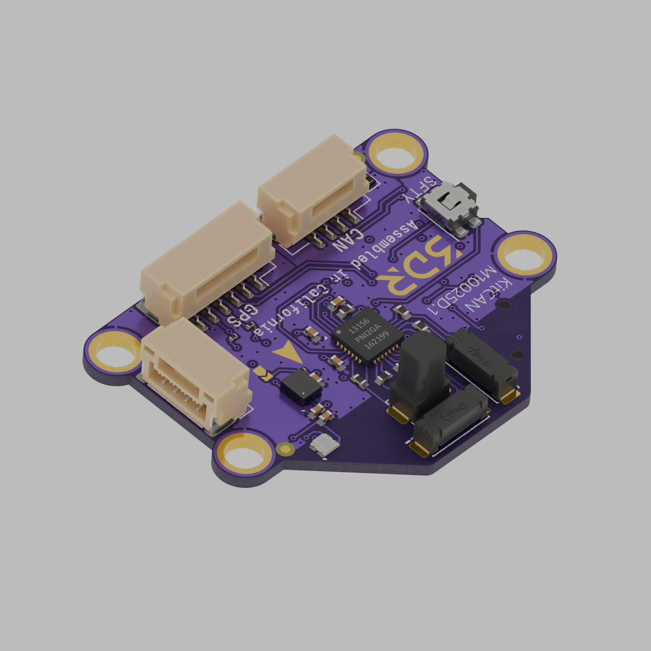
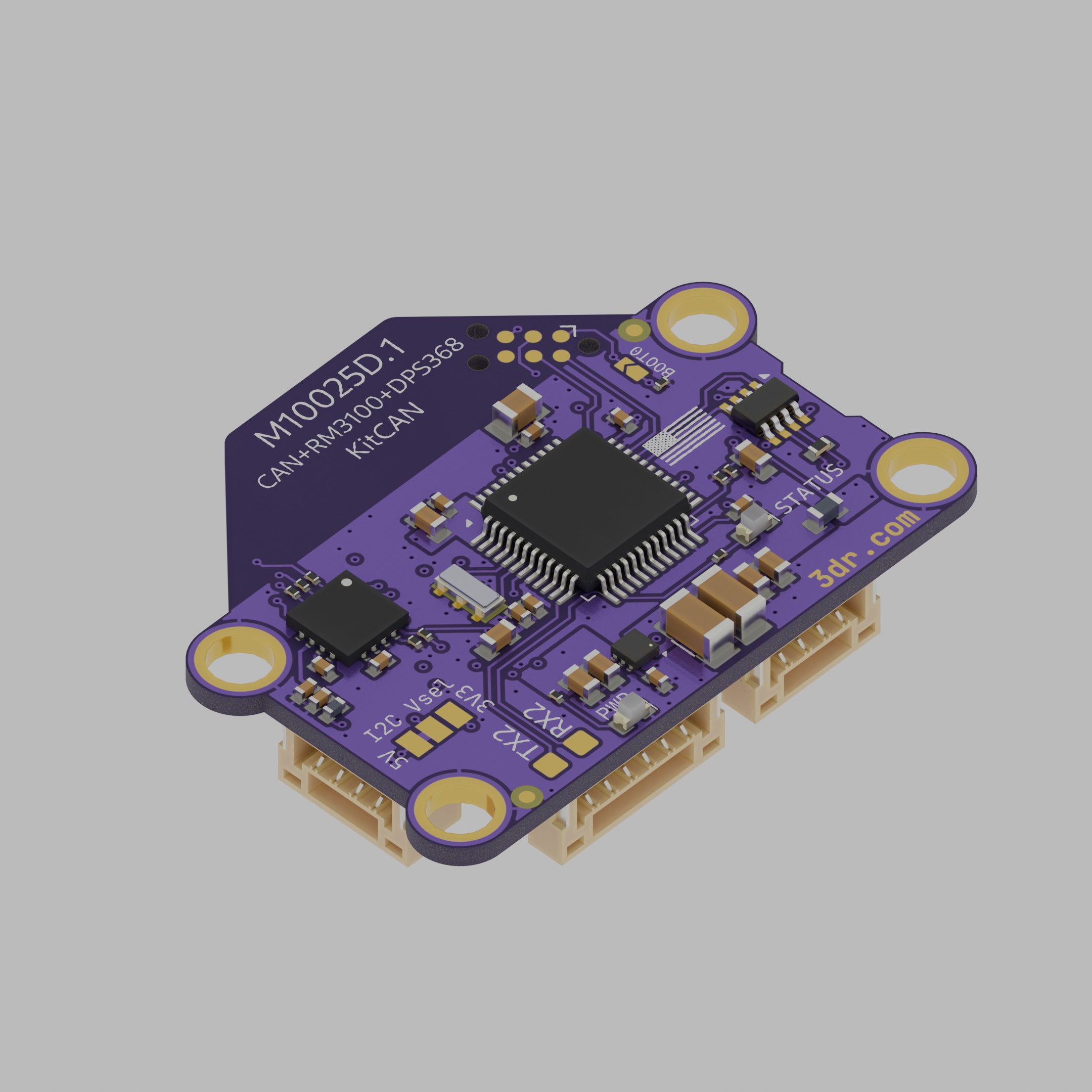
3D View
Specifications
| Electrical/MCU | KitCAN M10025 |
|---|---|
| Main processor | STM32F303 |
| Flash size | 256kB |
| Operating voltage | 5V |
| Maximum current (fused) | 250mA |
| Internal 3v3 reg current | 400mA |
| I2C pull-ups | Installed (2k2) |
| CAN termination resistor* | Installed |
| Mechanical | |
|---|---|
| Dimensions | 35.5mm x 27mm |
| Screw pattern | 30.5mm x 14mm |
| Screw size | M3 (3.2mm hole diameter) |
| Board thickness | 1.2mm (1.0mm rev B) |
| Weight | 3.5 grams |
Tip
A modified version without termination resistor is available upon request for large orders.
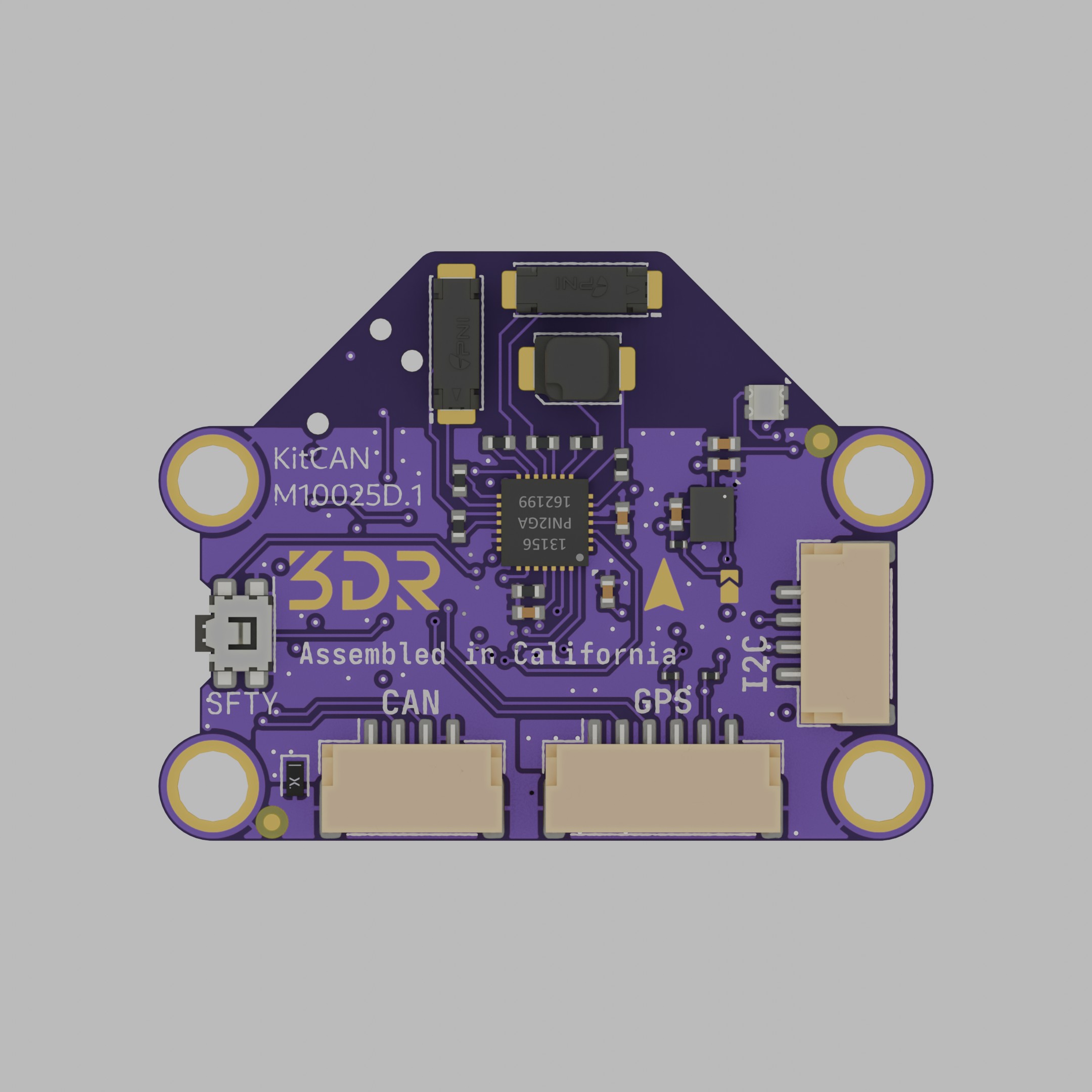
Graphical pinout diagram
Front side


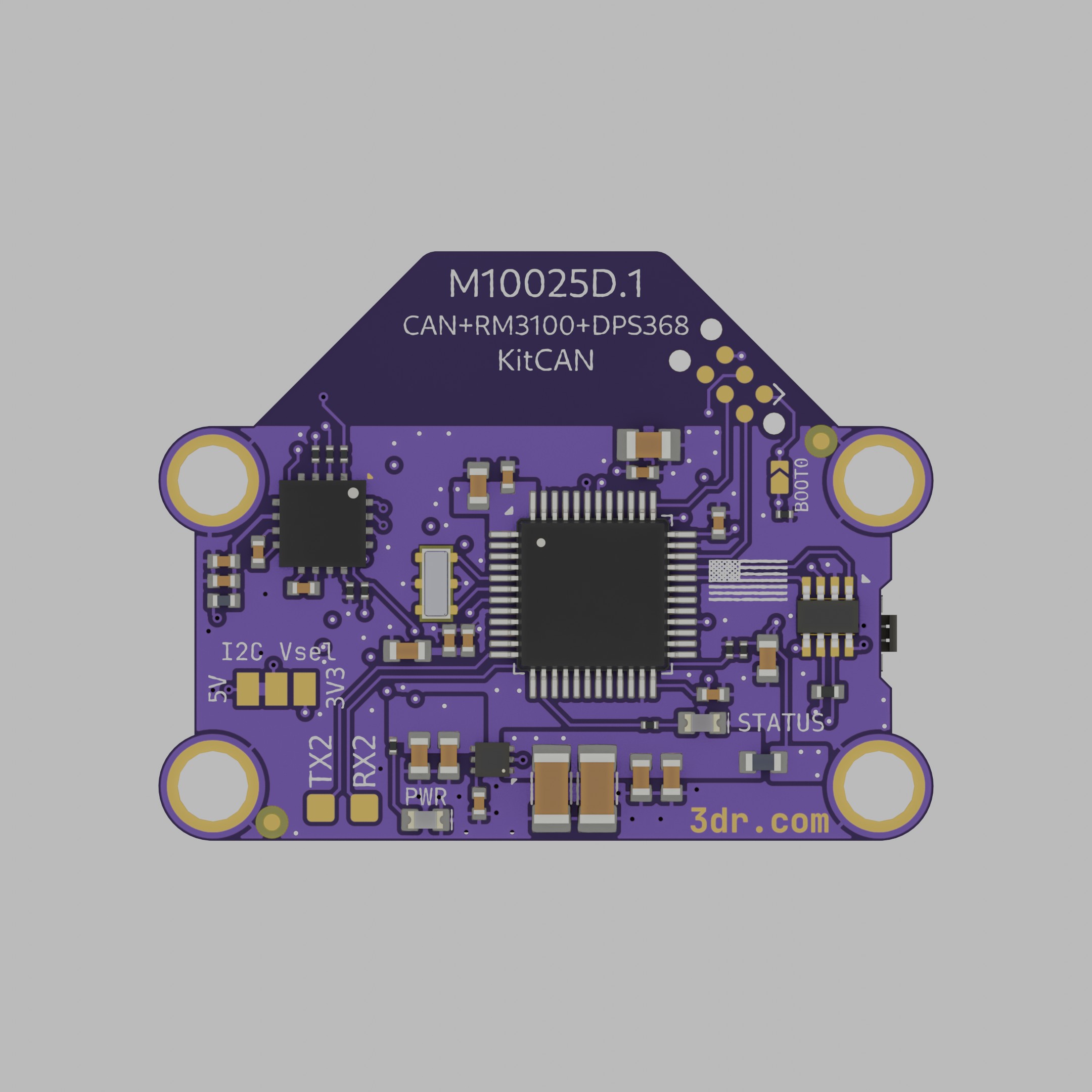
Back side
The software update that came with revision C also enables UART2 pads on the bottom of the board, as pictured in the following figure.
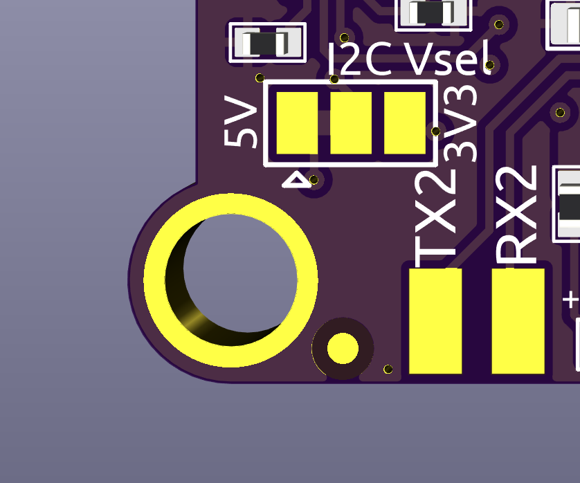
You will notice a new solder jumper on the back labeled as I2C_VSEL, which enables support for 3.3V only I2C peripherals since many sensor breakout boards have this characteristic. If you want to enable the 3V3 output, you will have to cut the trace with a hobby knife or a similar tool and apply a solder blob from the 3V3 labeled side of the jumper to the center pad.
Warning
After removing the trace make sure there is no short between the 3V3 and 5V nodes, as this will cause irreversible damage to the board.
Changelog
The changelog for this product can be found at this link.
Quick Start
KitCAN board is intended to work as a sensor-enriched CAN node so the use cases are diverse. If all you need is the external magnetometer and baro, using a 4-wire JST-GH cable of any length is enough to get up and running. Adding external sensors or modules is a plug and play experience as the extra peripherals will be picked up upon the next boot.
Firmware compatibility
Revision C boards introduce a different routing to reduce inductance. This improves the e-compass performance but breaks compatibility with older firmware versions.
Boards Revision B and older require the legacy f303-M10025 firmware target. Boards Revision C and D require the newer KitCAN rev C_D AP_Periph firmware target.
If you have a Revision B or older and want to update firmware manually, please use the firmware target below.
And if you have a Revision C or D board and want to update firmware manually, please use the firmware target below.
![]()
Parameters
Make sure you are using the latest version of Mission Planner. With the following firmware versions or newer:
| Parameter | Value |
|---|---|
| ArduPlane | V4.0.5 |
| ArduCopter | V4.0.3 |
| ArduRover | V4.0.0 |
Go to Full Parameter Tree on Mission Planner and verify the following are enabled:
| Parameter | Value |
|---|---|
CAN_P1_DRIVER | 1 |
GPS_TYPE | 9 UAVCAN |
Make sure the UAVCAN compass driver is not disabled (UAVCAN should be unchecked).
If your controller has more than 3 internal compasses, you should disable the least important one:
| Parameter | Value |
|---|---|
COMPASS_TYPEMASK | UAVCAN (Unchecked) |
The RGB notify LED via DroneCAN needs to be enabled by selecting bit 5 of NTF_LED_TYPES parameter, or just select the "DroneCAN" checkbox in the popup window.
I2C Airspeed sensor
If you want to enable the I2C airspeed, on the autopilot/controller parameters via Mission Planner set ARSPD_TYPE = 8 UAVCAN
Use the following parameters depending on the type of airspeed you are connecting.
ARSPD_TYPE = 1For I2C Airspeed Sensor JST-GH MS4525DOARSPD_TYPE = 4For MS5525
Port pinout tables
GPS Port
| Pin | Color | Signal | TTL/Voltage Level |
|---|---|---|---|
| 1 | red | VCC | 5V |
| 2 | black | TX | 3V3 |
| 3 | black | RX | 3V3 |
| 4 | black | I2C_SCL | 3V3 |
| 5 | black | I2C_SDA | 3V3 |
| 6 | black | GND | N/A |
CAN Port
| Pin | Color | Signal | TTL/Voltage Level |
|---|---|---|---|
| 1 | red | VCC | 5V |
| 2 | black | CAN_H | 5V |
| 3 | black | CAN_L | 5V |
| 4 | black | GND | N/A |
I²C Port
| Pin | Color | Signal | TTL/Voltage Level |
|---|---|---|---|
| 1 | red | VCC | 5V |
| 2 | black | I2C_SCL | 3V3 |
| 3 | black | I2C_SDA | 3V3 |
| 4 | black | GND | N/A |