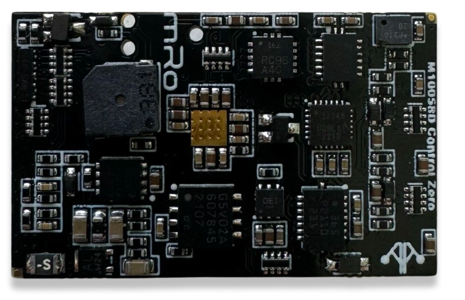
Control Zero H7 - M10058 
Description
The Control series of flight controllers from 3DR is our commitment to continuous improvement. Our goal with this series was to take every lesson learned from our +10 years of flight controller design and make the best pro-consumer and commercial flight controller on the market.
Purchase Control Zero H7 Kit Purchase Aluminum Case
Specifications
| Specifications | Control Zero H7 |
|---|---|
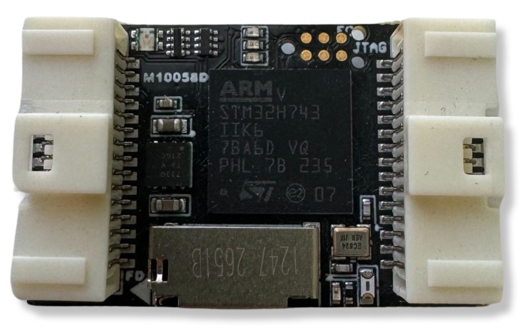
| Main Processor | STM32H743 Arm® Cortex®-M7 core (with double-precision floating point unit). 480 MHz |
| IO Coprocessor | No |
| RAM | 1 MB |
| Flash | 2 MB |
| FRAM | 256kb |
| Accelerometers / Gyros / Mags | 3x Accelerometers , 3x Gyros, 1x Magnetometer |
| Sensors | Bosch BMI088 (6DoF) Invensense/TDK ICM-20602 (6DoF) Invensense/TDK ICM-20948 (9DOF) |
| Internal Magnetometer | AK09916 inside ICM-20948 |
| Barometer | Infineon DPS310 barometer (Very smooth and NO light sensitivity) |
| Interfaces and Protocols | 5x UART (serial ports) [2x with HW flow control]. 1x PPM sum input signal 8x PWM outputs (all DShot capable) 1x RSSI (PWM or voltage) input 1x I2C 1x SPI 1x CAN 1x JTAG (TC2030 Connector) 3x Ultra low noise LDO voltage regulator Supported RC input protocols: Spektrum DSM / DSM2 / DSM-X® Satellite compatible input and binding. Futaba S.BUS® & S.BUS2® compatible input. FRSky Telemetry port output. Graupner SUMD. Yuneec ST24. |
| Connectors | -Molex PicoClasp -External MicroUSB |
| Pin Headers | Yes |
| Conformal Coating | Yes |
| Extended Testing and Burn In | Yes |
| Custom Carrier Board Support | No |
| NotifyLED | Yes (RGB) |
| Dimensions | Width: 25.9mm (1.01”) Length: 40mm (1.57”) Height: 13.2 mm (0.52in) |
| Dimensions w/o case | Width: 20mm (0.79") Length: 32mm (1.26") Height: 10.5 mm (0.41") |
| Weight | 34.94g (1.23 oz) |
| Weight w/o case | W/ Pins: 18.14g (0.64 oz), W/o Pins 13.04g (0.46 oz) |
| Mounting Holes | N/A |
| Protector Case | Included aluminum case |
| Typical Platforms | -Multirotor -Rover -Fixed-Wing -Boats -Submarines -VTOL -Automatic Tractors -Others |
About IO coprocessors and AUX Pins
Historically, microcontrollers mounted on Autopilots didn't have enough resources to handle the requirements that industry was demanding. Usually, the features needed to keep up with the trends, pushed manufacturers to add IO coprocessors to increase the number of available timers to generate and decode PWM signals and additional IO Pins. The coprocessor in these hardware architectures is usually connected via a single serial port, reducing the amount of data available in time and introducing more points of failure. This arrangement pushed the pins to be divided by MAIN and AUX Pins, where MAIN were the pins connected to the MCU and AUX to IO coprocessors. However, later generations of hardware have increased IO pin density, timers and reduced size factor, among other enhancements. Additionally, a special benefit also stands out for our design principles, and it is the higher amount and more sophisticated DMAs that work really well with peripherals, transferring high amounts of data and decreasing CPU usage. Besides, we are transitioning from a single MCU architecture to more distributed systems thanks to DroneCAN and Ethernet connectivity (coming soon). In practical terms, you can consider every available PWM pin in your board as you would for an AUX pin.
Firmware
The mRo Control Zero is compatible with the following firmware:
Ardupilot

PX4

Normal Usage Guide
All connectors follow the Dronecode connector standard. Unless noted otherwise, all connectors are JST-GH.
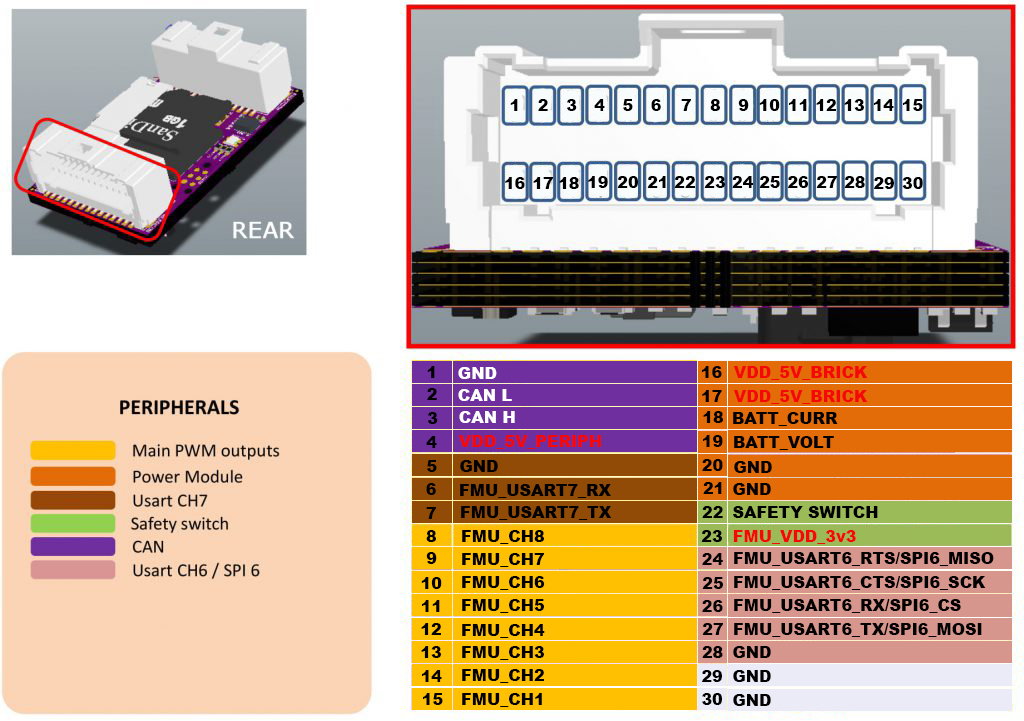
Pinouts
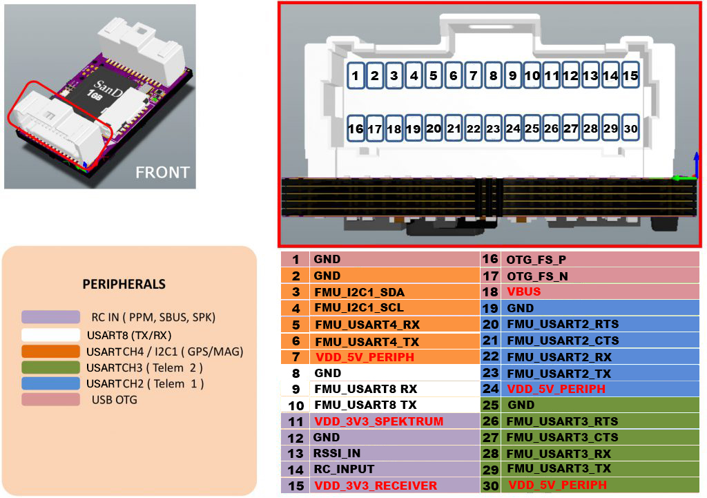
The serial ports default assignment is as follows:
| Serial | Port Name | AP Serial |
|---|---|---|
| USART2 | TELEM1 | SERIAL1 |
| USART3 | TELEM2 | SERIAL2 |
| USART4 | GPS | SERIAL3 |
| USART8 | Additional UART | SERIAL4 |
| USART7 | Additional UART | SERIAL5 |
Custom builds may be needed if you want to change default functionality for UART/SPI 6, this depends on the selected flight stack firmware.*
If you have further questions contact us.
Power considerations
The board is intended to be powered either from the power 'brick' labeled as 5V_SRC in the above diagram or the VUSB pin or both; 5.25V is recommended due to protection diodes, this way you'll avoid getting low voltage warnings from the ground station software. The CZ OEM is able to provide up to 1.8A (fused) to the 5V_PRPH power domain, exceeding this current is will damage the board.
%%{init: {'theme':'dark'}}%%
flowchart LR
    in1>5V_BRICK] -->|2.5A fuse| n1(OR-diode)
    in2>USB_VBUS] --> n1
    n1 --> vin{"`5V_IN
    (PWR_LED)`"}
    vin --> |1A LDO| int1([FMU_VDD_3V3])
    vin --> |Schottky| out1[5V_RECEIVER]
    vin --> |"SPEKTRUM_POWER [PE4]"| out3[VDD_3V3_SPEKTRUM]
    vin --> |Fused ~500mA| out2[VDD_5V_PERIPH]
    subgraph Inputs
        in1
        in2
    end
    subgraph Power outputs
        out2
        out1
        out3
    end
Tutorials
Accessories Bags
Bag #1
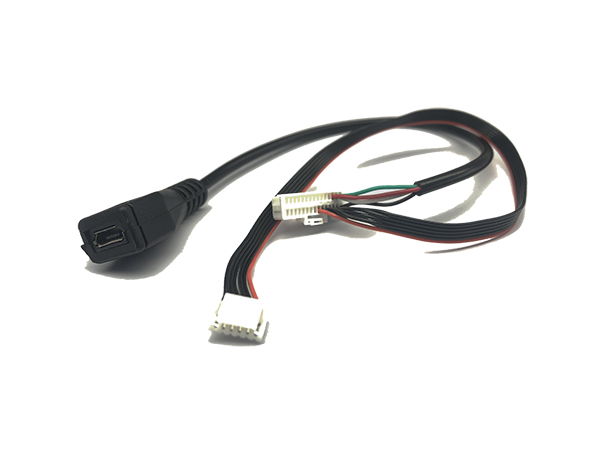
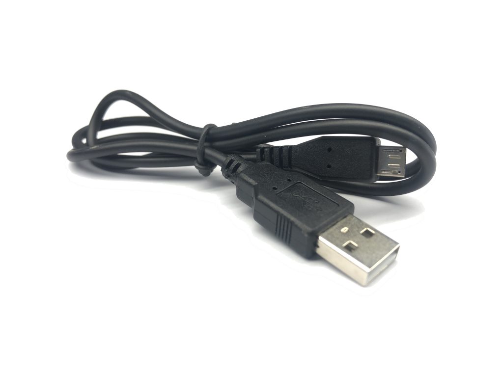
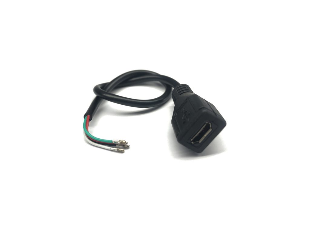
Bag #1 contains the [30P-PicoClasp Header + MRC0272 + MRC0277] combined with the [Micro USB Cable], which offers a quick way to attach your autopilot to your PC. The MRC0272 is the female USB cable socket and the MRC0277 is the 6-position, red and black cable with a JST-GH header to attach your GPS. We recommend always keeping this harness on the ground and only using it for quick testing, firmware updates, and/or diagnosis.
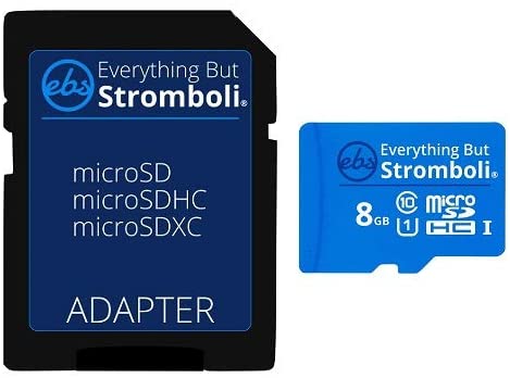
This bag also contains the enclosure (optional) and SD Card.
Warning
Note that depending on the SD Card packaging dimensions, it might sometimes be located outside the bag.
- 1 x Micro USB Cable
- 1 x 30P-PicoClasp Header + MRC0272 + MRC0271: 6P-PicoClasp Crimps to 6P-JST-GH Header (Red&Blk)
- 1 x 8GB SD Card
- 1 x Control Zero Case
- 1 x Tweezer
Bag #2
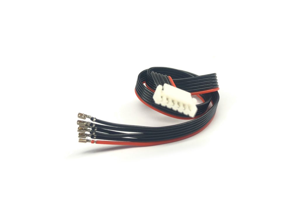
This bag contains 2x red and black MRC0271 cables that will allow you to quickly attach your GPS and/or Telemetry modules that are JST-GH compatible. Please refer to Bag #3 for more PicoClasp to JST-GH options.
The remaining white cables [MRC0274, 5, 6 & 7] have PicoClasp crimps on one side and a “bare” cable on the other. Those are optional cables that allow advanced users to solder them to other hardware, or for pure development purposes.
- 2 x MRC0271: 6P-PicoClasp Crimps to 6P-JST-GH Header
- 1 x MRC0272: 4Pos-PicoClasp to Female Micro USB Socket
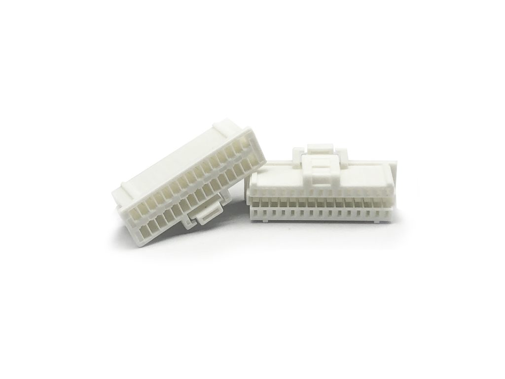
- 4 x 30P-PicoClasp Headers
Bag #3
This bag contains everything that is needed to assemble your own custom harnesses and interface between the two onboard Control Zero 30-pin PicoClaps connectors to the standard JST-GH header with 4 and 6 positions. The JST-GH is commonly used for CAN, GPS, Telemetry, and Power modules.
We have included enough “pre-crimped” PicoClaps to JST-GH cables with different lengths and JST-GH Housings to allow you to build any possible configuration. You won’t use most of the cables included, they are just there to give you maximum flexibility. You can obtain more housings at our store to take advantage of the remaining cables, or you can just save them as spare parts.
- 3 x 4P-JST-GH Housing
- 6 x 6P-JST-GH Housing
- 1 x MRC0279-150mm: 6P-PicoClasp Crimps to JST-GH Crimps
- 1 x MRC0280-50mm: 12P-PicoClasp Crimps to JST-GH Crimps
- 1 x MRC0280-100mm: 12P-PicoClasp Crimps to JST-GH Crimps
- 1 x MRC0280-200mm: 12P-PicoClasp Crimps to JST-GH Crimps
Bag #4
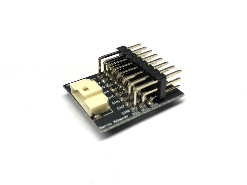
This bag contains everything needed to create your own harnesses to attach servos to the Control Zero autopilot. Use the M10067 board to interface with standard 2.54 mm servos, or the M10068 board for the standard mini-servo connector. With some creativity, both boards can be used simultaneously to control a mix of standard and mini servos.
Warning
Note that not all of the MRC0281-xxx cables are expected to be used; choose the length that best fits your needs. The M10068 board is sold separately on our webpage.
- 2 x 10P-PicoClasp Housing
- 1 x MRC0281-50mm: 12P-PicoClasp Crimp to PicoClasp Crimp
- 1 x MRC0281-100mm: 12P-PicoClasp Crimp to PicoClasp Crimp
- 1 x MRC0281-300mm: 12P-PicoClasp Crimp to PicoClasp Crimp
- 1 x M10067 (Board): 10P-PicoClasp Housing to 8x Servo Header
Harness Assembly
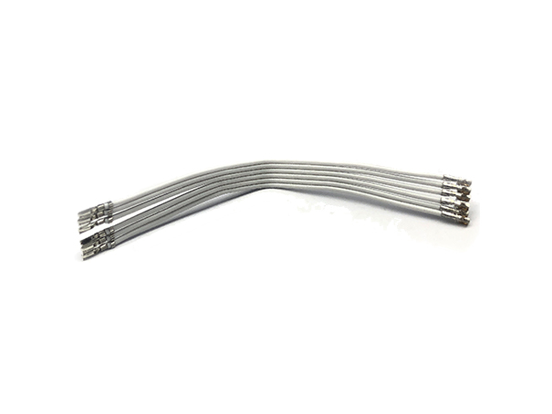
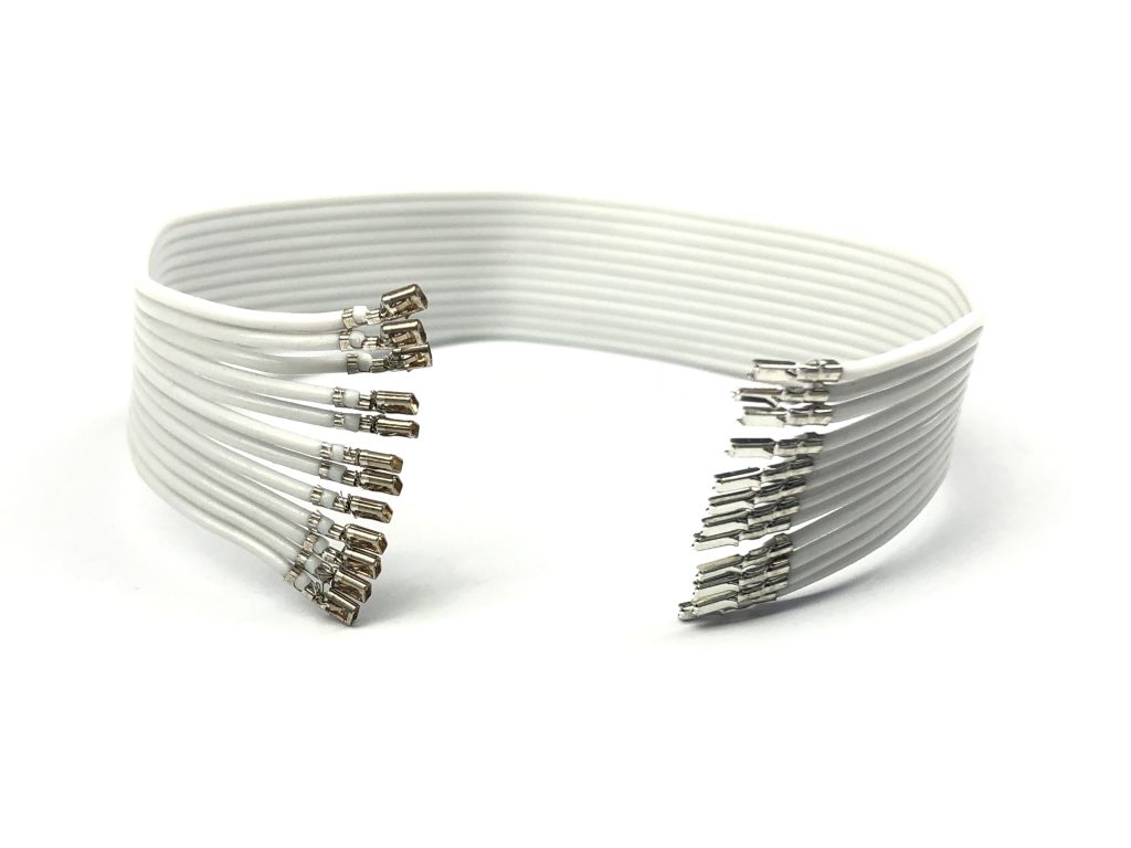
Pico-Clasp Crimp Terminal
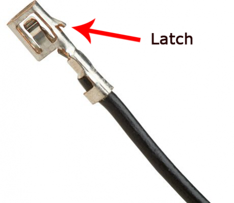
This is the Terminal Crimp that is included in each end of the cables.
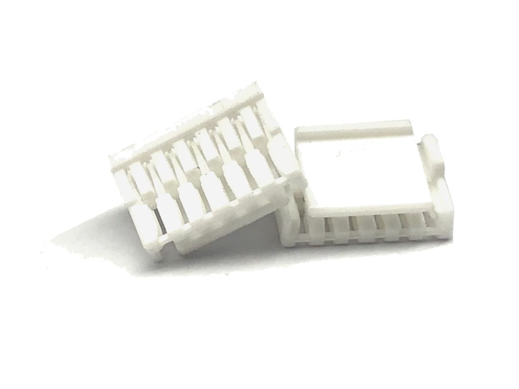
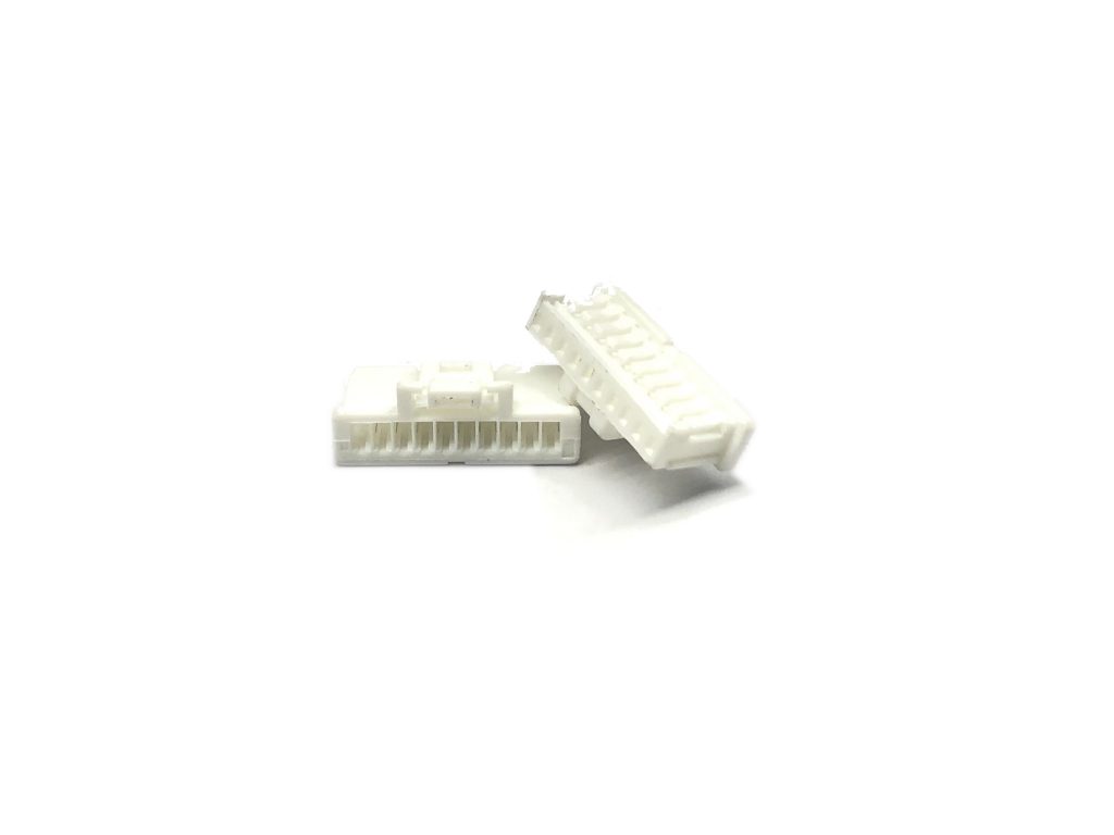
Molex Pico-Clasp Connector
Most of the cables are just “pre-crimped” with PicoClaps crimps. They must be inserted into the “connector” with the correct direction of the latch.
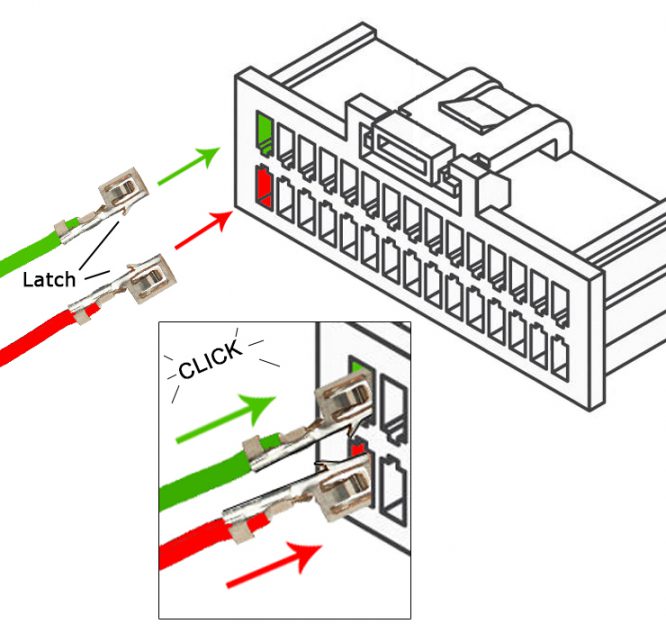
Tip
Notice that the metal Crimp has a little metal “latch” sticking out, the latch goes into the “inner” part of the connector above, you will see that the hole is rectangle and you have a little opening pointing to the middle of the housing, that is where you insert the latch. Make sure it goes all the way in, no metal should be sticking out of the connector
Accesories
Questions or something missing? Please emails us at: info@3dr.com