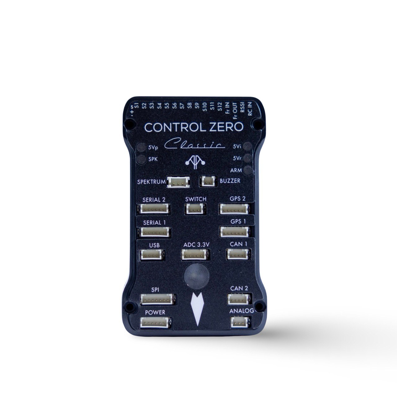
Control Zero Classic - M10048 
Description
The Control Zero series of flight controllers represents 3DR's commitment to continuous improvement. Our goal with this series was to take every lesson learned from our +10 years of flight controller design and make the best pro-consumer and commercial flight controller on the market. With the Classic form factor, we try to still support the tried and tested Pixhawk 1 form factor and connector set, while bringing a modern feature and sensor set to the table.
Specifications
| Specifications | Control Zero Classic |
|---|---|
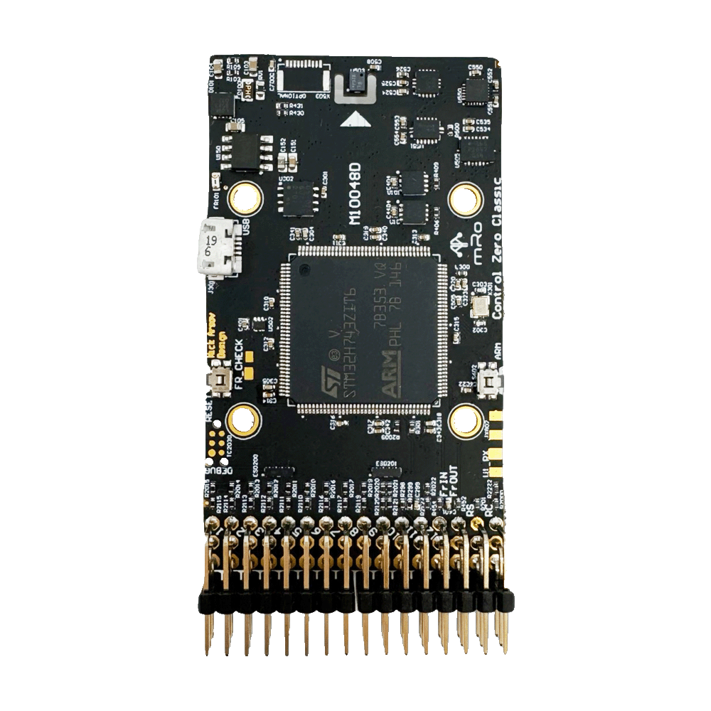
| Main Processor | 32-bit STM32H743 Cortex M7 core with DSP and DP-FPU, max frequency 480 MHz |
| IO Processor | No |
| RAM | 1MB RAM |
| Flash | 2 MB |
| FRAM module | 256kb - for parameters only |
| Accelerometers / Gyros / Mags | 3x Accelerometers / 3x Gyros / 1x Mag |
| Sensors | Bosch BMI088 (6DoF) Invensense/TDK ICM-20602 (6DOF) Invensense/TDK ICM-20948 (9DoF) |
| Internal Magnetometer | AK09916 inside ICM-20948 |
| Barometer | Infineon DPS310 barometer (Very smooth and NO light sensitivity) |
| Interfaces and Protocols | 5x UART (serial ports) [2x with HW flow control, 2x GPS+I2C, 1x FRSky Telemetry (D or X types)]. 1x PPM sum input signal 12x PWM outputs 1x RSSI (PWM or voltage) input 2x I2C 1x SPI 2x CAN 1x SWD (TC2030 Connector) Supported RC input protocols: Spektrum DSM / DSM2 / DSM-X® Satellite compatible input and binding. Futaba S.BUS® & S.BUS2® compatible input. FrSky Telemetry port output. Graupner SUMD. Yuneec ST24. |
| Mating Connectors | DF-13 |
| Pin Headers | Yes |
| Conformal Coating | Optional |
| Notify LED | Yes (RGB) |
| Dimensions | Width: 40mm (1.57″) Length: 70mm (2.76″) |
| Dimensions with Case | Width: 49.5mm (1.95") Length: 81.5mm (3.21") Height: 15mm (0.59") |
| Weight | 4.14g (.15 oz) |
| Mounting Holes | No |
| Case | Included |
| Typical Platforms | - Multirotor - Rover - Fixed-Wing - Boats - Submarines - VTOL - Automatic Tractors - Others |
| Electrical | 5.25V @200mA minimum, 2A recommended |
About IO coprocessors and AUX Pins
Historically, microcontrollers mounted on Autopilots didn't have enough resources to handle the requirements that industry was demanding. Usually, the features needed to keep up with the trends, pushed manufacturers to add IO coprocessors to increase the number of available timers to generate and decode PWM signals and additional IO Pins. The coprocessor in these hardware architectures is usually connected via a single serial port, reducing the amount of data available in time and introducing more points of failure. This arrangement pushed the pins to be divided by MAIN and AUX Pins, where MAIN were the pins connected to the MCU and AUX to IO coprocessors. However, later generations of hardware have increased IO pin density, timers and reduced size factor, among other enhancements. Additionally, a special benefit also stands out for our design principles, and it is the higher amount and more sophisticated DMAs that work really well with peripherals, transferring high amounts of data and decreasing CPU usage. Besides, we are transitioning from a single MCU architecture to more distributed systems thanks to DroneCAN and Ethernet connectivity (coming soon). In practical terms, you can consider every available PWM pin in your board as you would for an AUX pin.
Quick start
The board comes with Ardupilot stable pre-installed from factory. However, the bootloader provides an interoperation layer with PX4 as well, so QGC will be able to detect it and load firmware adequately.
We encourage all customers to run the latest stable version available from your preferred flight stack.
Firmware
The 3DR Control Classic is compatible with the following firmware:
ArduPilot
- compatible with all vehicle types.
PX4
PX4 v1.14 support for this board is now available!
 - compatible with all vehicle types.
Some additional resources:
Top-View Pinout
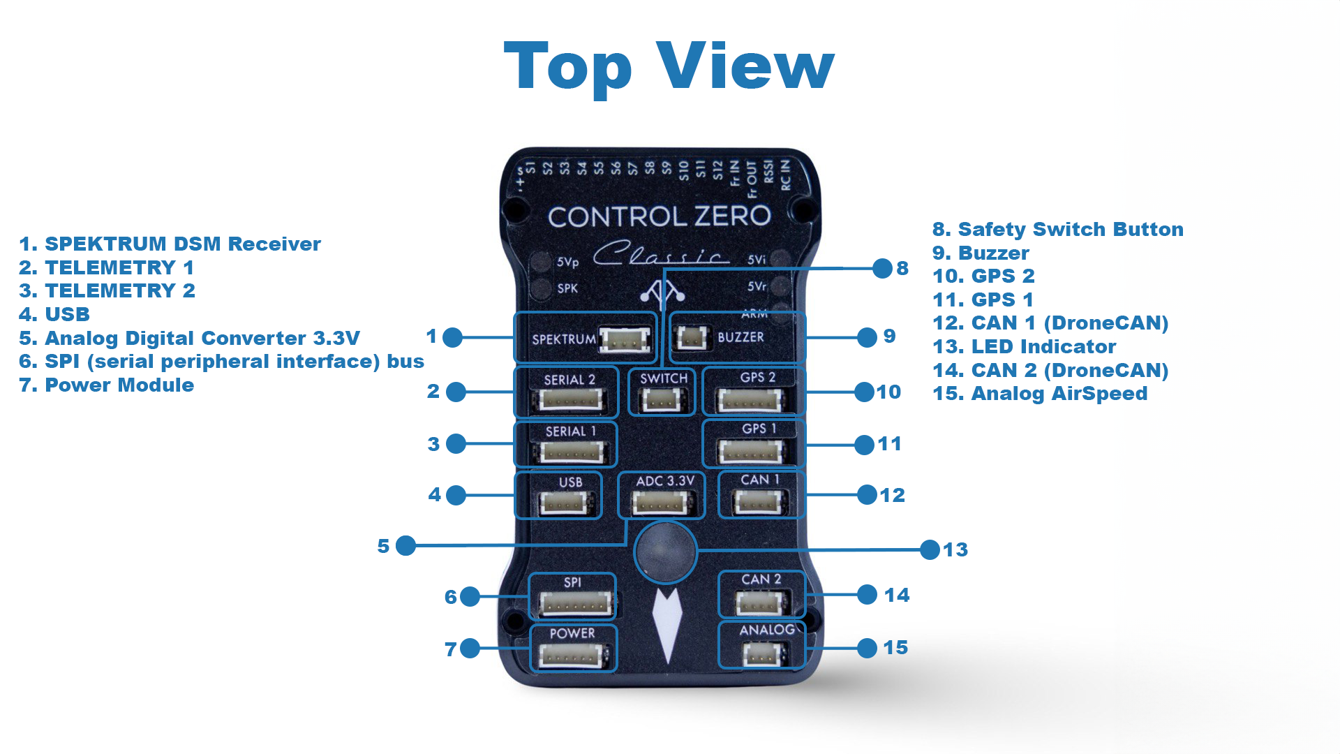
Important
CAN2 has replaced the I2C port, ignoring this message may damage your board.
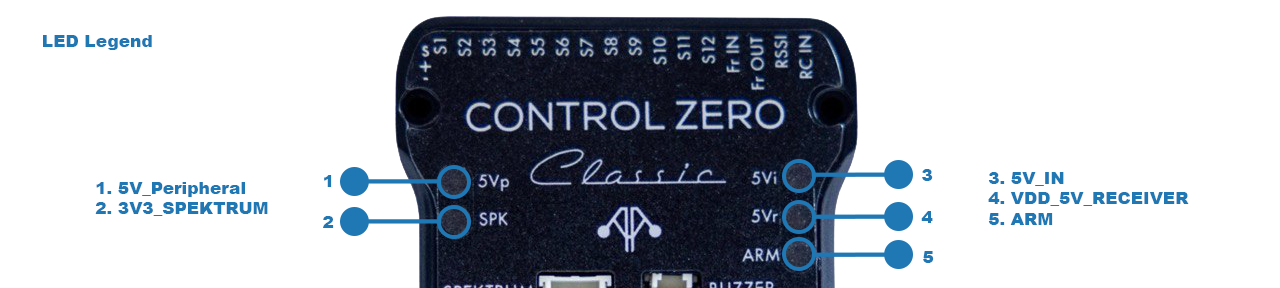
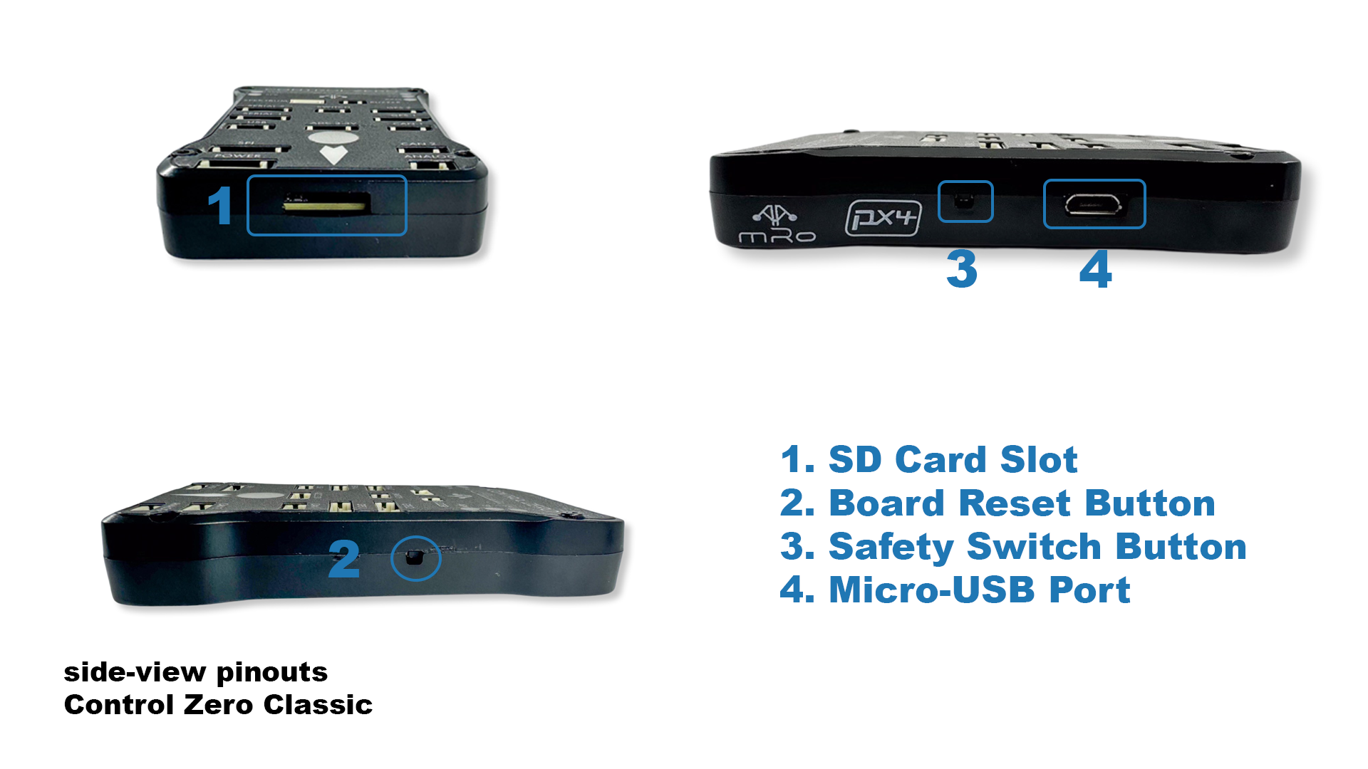
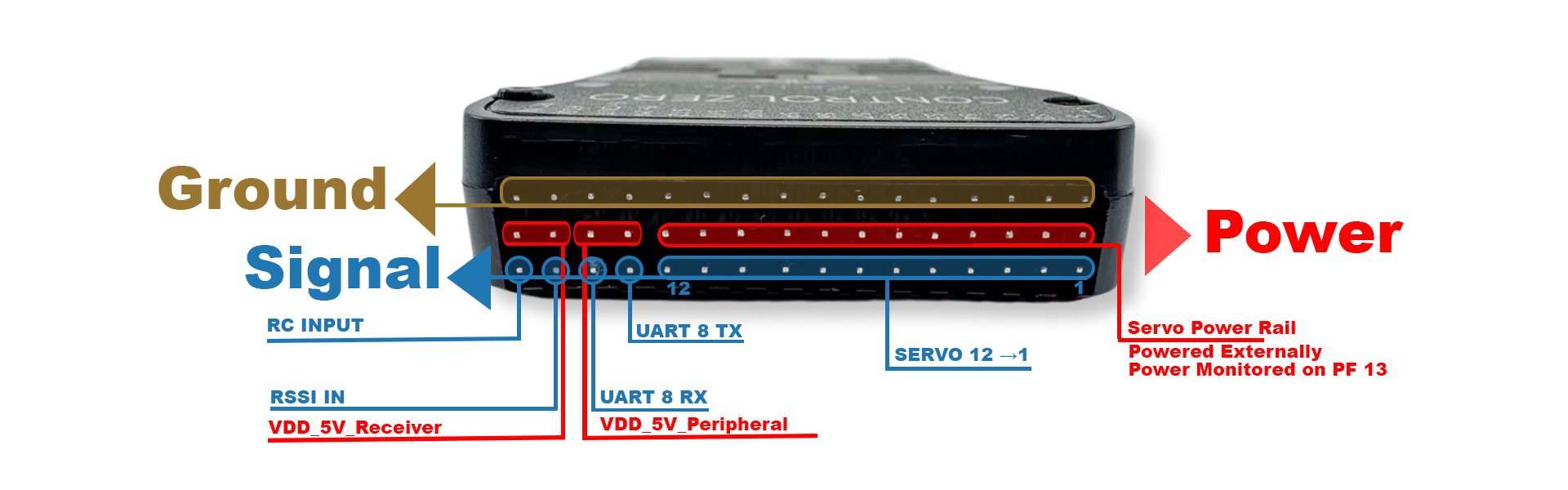
Side-View Pinouts
The serial port's default assignment is as follows:
| Serial | Port name | AP Serial |
|---|---|---|
| USART2 | TELEM1 | SERIAL1 |
| USART3 | TELEM2 | SERIAL2 |
| USART4 | GPS1 w/ I2C1 | SERIAL3 |
| USART7 | GPS2 w/ I2C4 | SERIAL4 |
| USART8* | Additional UART* | SERIAL5 |
| USART1** | Additional UART** | SERIAL6 |
- Originally labeled FrSky IN and FrSky OUT*
- Internal pad RX ONLY**
Connector pin assignments
TELEM1, TELEM2 ports
| Pin | Signal | Volt |
|---|---|---|
| 1 (red) | VDD_5V_Peripheral | +5V |
| 2 (blk) | TX (OUT) | +3.3V |
| 3 (blk) | RX (IN) | +3.3V |
| 4 (blk) | CTS | +3.3V |
| 5 (blk) | RTS | +3.3V |
| 6 (blk) | GND | GND |
GPS ports
This port is intended for combined serial plus I2C GPS units.
| Pin | Signal | Volt |
|---|---|---|
| 1 (red) | VDD_5V_Peripheral | +5V |
| 2 (blk) | TX (OUT) | +3.3V |
| 3 (blk) | RX (IN) | +3.3V |
| 4 (blk) | I2C_SCL | +3.3V |
| 5 (blk) | I2C_SDA | +3.3V |
| 6 (blk) | GND | GND |
ADC 6.6V
| Pin | Signal | Volt |
|---|---|---|
| 1 (red) | VDD_5V_Peripheral | +5V |
| 2 (blk) | ADC IN | up to +6.6V |
| 3 (blk) | GND | GND |
ADC 3.3V
| Pin | Signal | Volt |
|---|---|---|
| 1 (red) | VDD_5V_Peripheral | +5V |
| 2 (blk) | ADC IN | up to +3.3V |
| 3 (blk) | GND | GND |
| 4 (blk) | ADC IN | up to +3.3V |
| 5 (blk) | GND | GND |
CAN1 & CAN2
| Pin | Signal | Volt |
|---|---|---|
| 1 (red) | VDD_5V_Peripheral | +5V |
| 2 (blk) | CAN_H | +12V |
| 3 (blk) | CAN_L | +12V |
| 4 (blk) | GND | GND |
Custom builds may be needed if you want to change default functionality for UART/SPI 6, this depends on the selected flight stack firmware.
If you have further questions contact us.