CN1 Carrier 2 - Longy
ActiveRev A.2
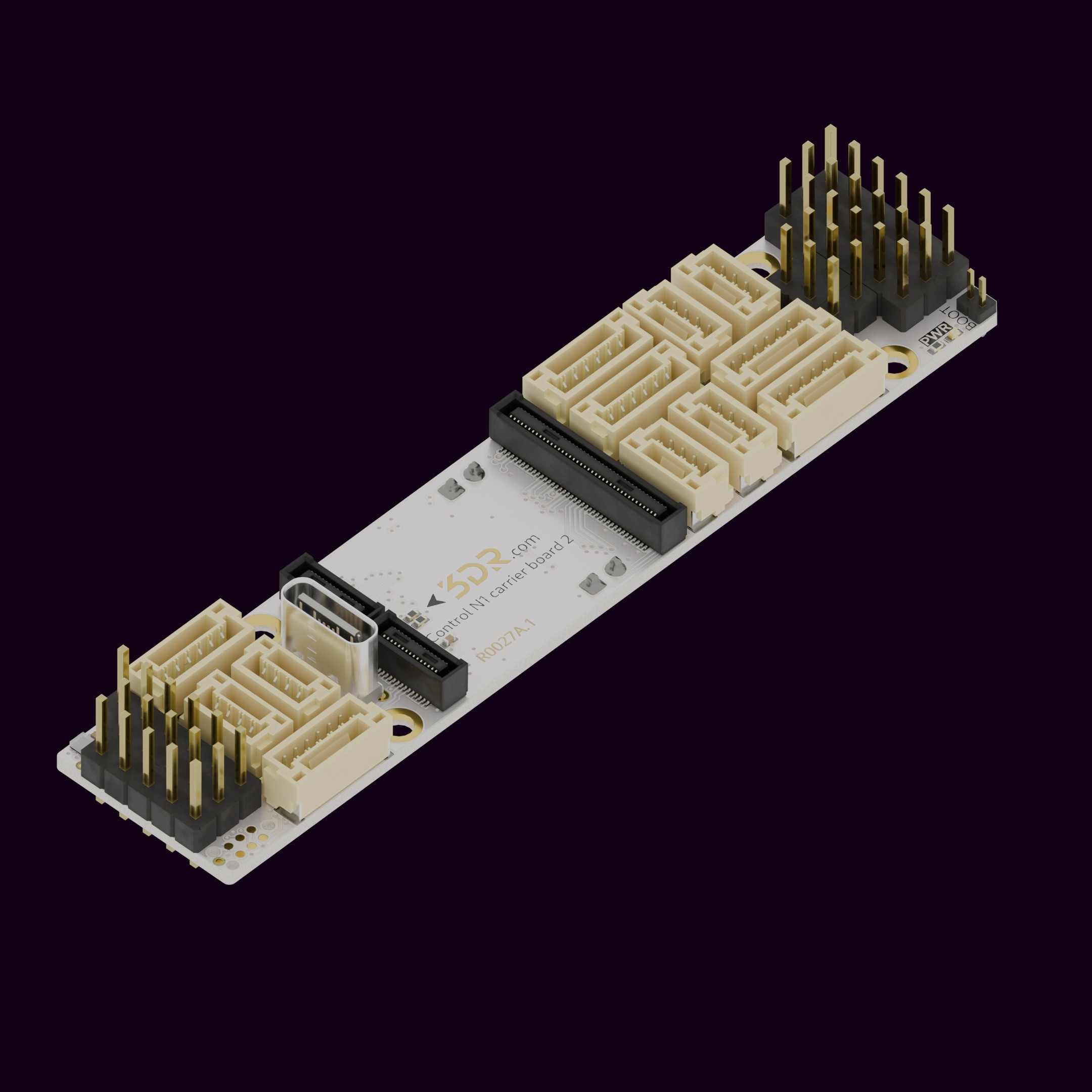
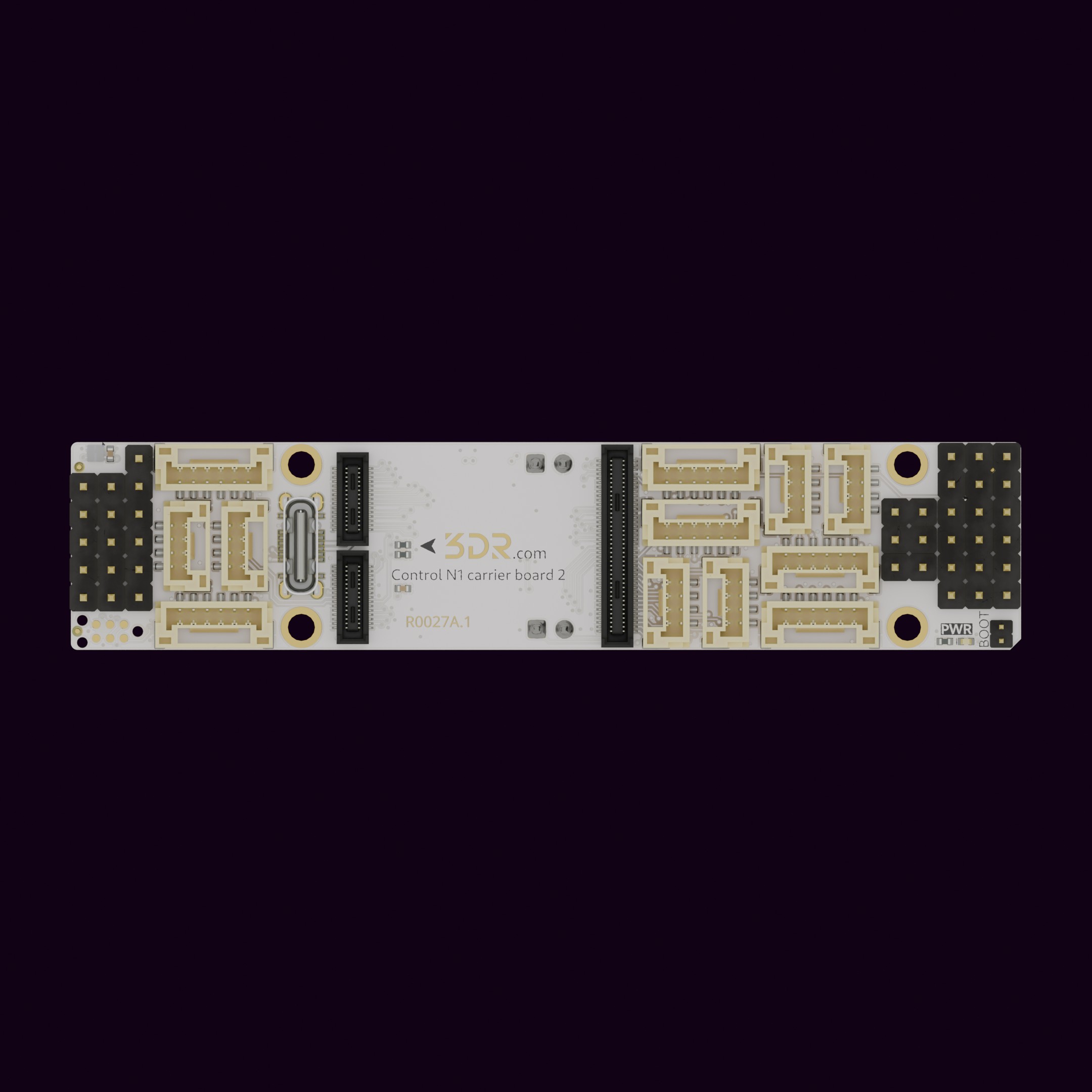
The Long-Form Factor CN1 Carrier Board “Longy” (R0027) is designed to expand the functionality of Control N1. Built on over 10 years of flight controller design and development experience.
Key Features
Section titled “Key Features”- Baseline Control N1 carrier board
- Compact design with a thin form factor — ideal for space constrained environments
- Plug-and-play compatibility — just connect and go
- Basic power management — single 5V power supply for FC and peripherals
3D View
Section titled “3D View”Loading 3D model…
Use Cases
Section titled “Use Cases”- Optimizing installations where space is limited but reach is essential
Installation & Setup
Section titled “Installation & Setup”- Unpack the product and inspect for any visible damage.
- Align the connector/interface with the corresponding port on Control N1.
- Secure the connection by pressing firm and equally both boards against each other.
- Power On the base product to verify successful integration.
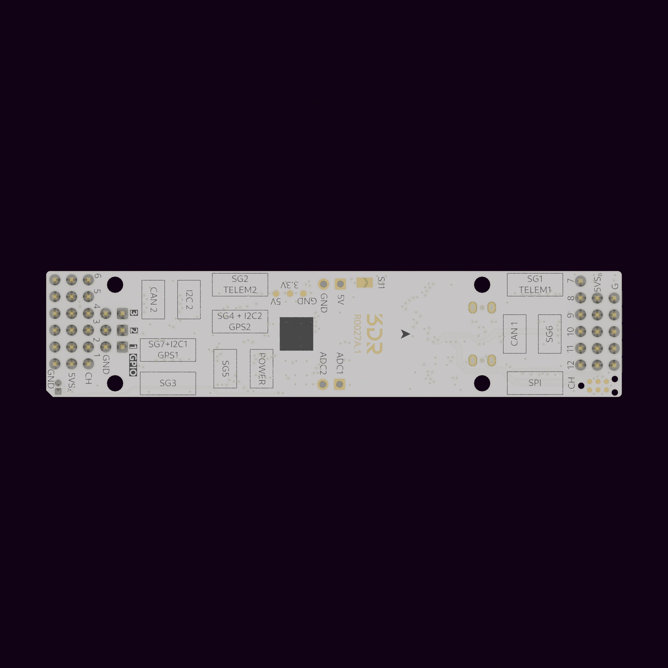
Available Ports
Section titled “Available Ports”- USB
- GPS1 (SG7 + I2C1)
- GPS2 (SG4 + I2C2)
- Serial 1 (SG1) w/Flow Control
- Serial 2 (SG2) w/Flow Control
- Serial 3 (SG3) w/Flow Control
- Serial 5 (SG5)
- Serial 6 (SG6)
- External SPI (SPI)
- I2C2 (I2C2)
- CAN1 (CAN1)
- CAN2 (CAN2)
- POWER (PWR, ADC1 + ADC2)
- ADC1 (ADC1)
- ADC2 (ADC2)
- BOOT0 (BOOT)
- SWD CLK/IO/RST (compatible w/ TC2030 connector)
- Servos (12 x PWM, BIDIR capable)
- IOs (3x GPIO)
To have a more detailed description of each pin, please use our Pinout tool.
Pinout tool
| Port | Name | Pin |
|---|---|---|
| USB | 5V | x |
| USB | USB_DM | x |
| USB | USB_DP | x |
| USB | GND | x |
| GPS1 | 5V | 1 |
| GPS1 | UART5_TX | 2 |
| GPS1 | UART5_RX | 3 |
| GPS1 | I2C1_SCL | 4 |
| GPS1 | I2C1_SDA | 5 |
| GPS1 | GND | 6 |
| GPS2 | 5V | 1 |
| GPS2 | USART3_TX | 2 |
| GPS2 | USART3_RX | 3 |
| GPS2 | I2C2_SCL | 4 |
| GPS2 | I2C2_SDA | 5 |
| GPS2 | GND | 6 |
| SG1 | 5V | 1 |
| SG1 | USART2_TX | 2 |
| SG1 | USART2_RX | 3 |
| SG1 | USART2_CTS | 4 |
| SG1 | USART2_RTS | 5 |
| SG1 | GND | 6 |
| SG2 | 5V | 1 |
| SG2 | UART4_TX | 2 |
| SG2 | UART4_RX | 3 |
| SG2 | UART4_CTS | 4 |
| SG2 | UART4_RTS | 5 |
| SG2 | GND | 6 |
| SG3 | 5V | 1 |
| SG3 | UART7_TX | 2 |
| SG3 | UART7_RX | 3 |
| SG3 | UART7_CTS | 4 |
| SG3 | UART7_RTS | 5 |
| SG3 | GND | 6 |
| SG5 | 5V | 1 |
| SG5 | USART1_TX | 2 |
| SG5 | USART1_RX | 3 |
| SG5 | GND | 4 |
| SG6 | 5V | 1 |
| SG6 | USART6_TX | 2 |
| SG6 | USART6_RX | 3 |
| SG6 | GND | 4 |
| SPI | 5V | 1 |
| SPI | SCK | 2 |
| SPI | MISO | 3 |
| SPI | MOSI | 4 |
| SPI | CS | 5 |
| SPI | GND | 6 |
| I2C2 | 5V | 1 |
| I2C2 | SCL | 2 |
| I2C2 | SDA | 3 |
| I2C2 | GND | 4 |
| CAN1 | 5V | 1 |
| CAN1 | CAN1_H | 2 |
| CAN1 | CAN1_L | 3 |
| CAN1 | GND | 4 |
| CAN2 | 5V | 1 |
| CAN2 | CAN2_H | 2 |
| CAN2 | CAN2_L | 3 |
| CAN2 | GND | 4 |
| PWR | 5V | 1 |
| PWR | ADC1 | 2 |
| PWR | ADC2 | 3 |
| PWR | GND | 4 |
| ADC1 | ADC 1 | 1 |
| ADC2 | ADC 2 | 1 |
| BOOT | 3V3 | 1 |
| BOOT | BOOT0 | 2 |
| SWD | 5V | 1 |
| SWD | SWDIO | 2 |
| SWD | RST | 3 |
| SWD | SWDCLK | 4 |
| SWD | GND | 5 |
| SWD | NC | 6 |
Graphical pinout
Section titled “Graphical pinout”
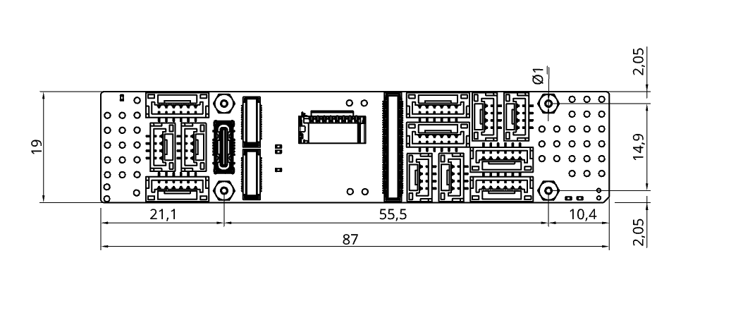
Mechanical information
Section titled “Mechanical information”| Mechanical Specifications | |
|---|---|
| Dimensions | Width: 19mm (0.74″) Length: 87mm (3.42″) Height: 8.3mm (0.32”) |
| Weight | 7.5g (0.27oz) |
Downloads
Section titled “Downloads”Maintenance
Section titled “Maintenance”- Clean with a dry cloth; avoid moisture or abrasive materials.
- Periodically check connection points for wear or loosening.
- Store in a cool, dry place when not in use.