Carrier board 2 for CN1 APM - R0027 
The Long-Form Factor CN1 Carrier Board “Longy” is designed to expand the functionality of Control N1 (R0024).
Built on over 10 years of flight controller design and development experience.
Key Features
- Baseline Control N1 carrier board
- Compact design with a thin form factor an ideal for space constrained environments
- Plug-and-play compatibility - just connect and go
- Basic power management - single 5V power supply for FC and peripherals
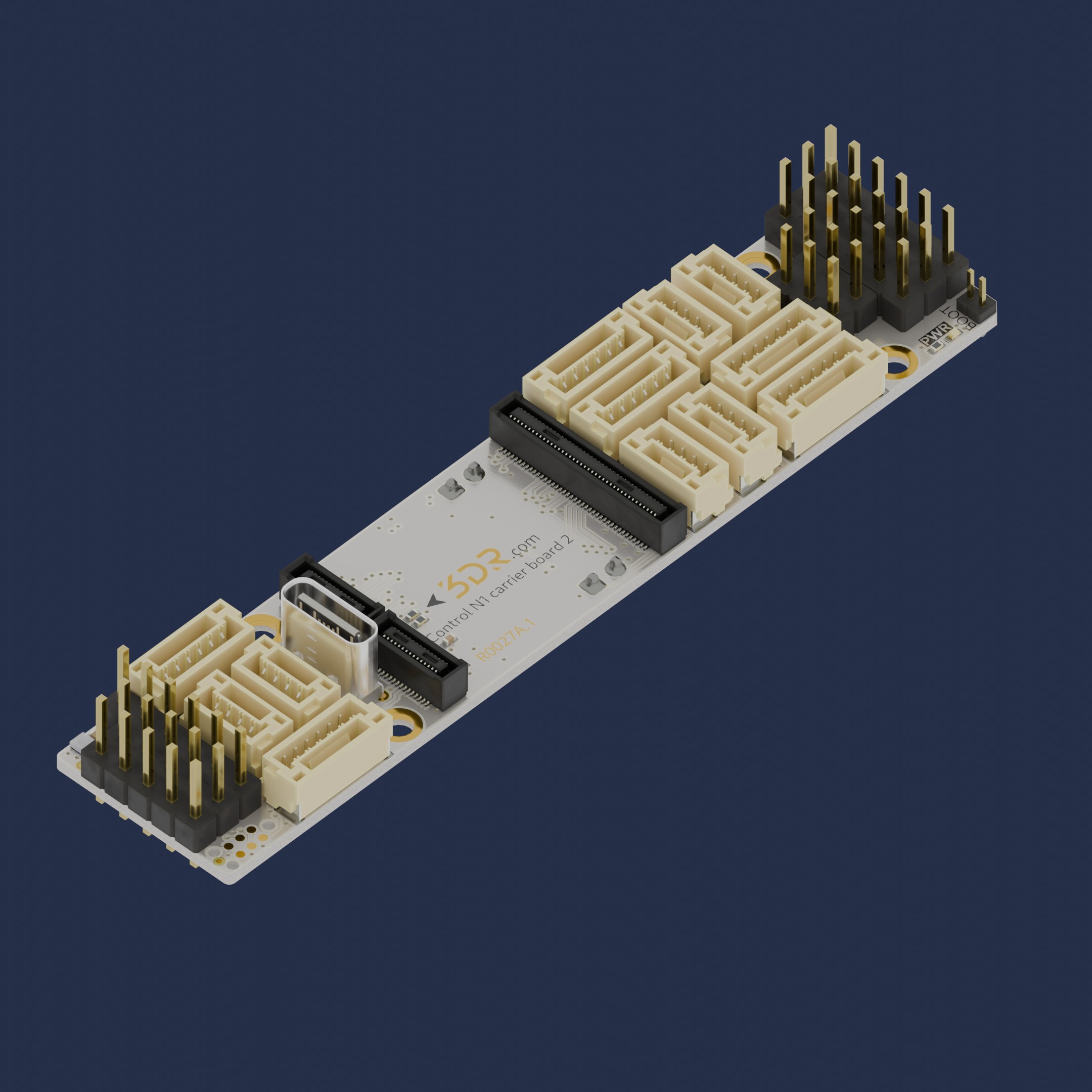
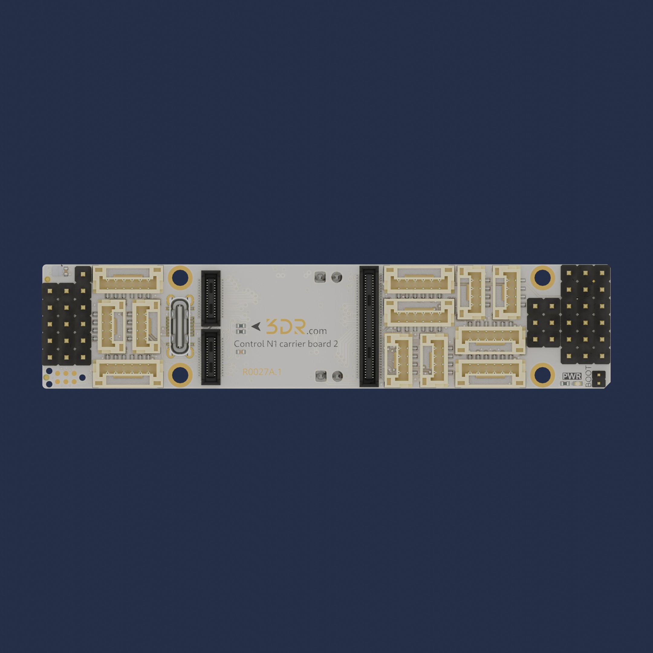
3D View
Use Cases
- Optimizing installations where space is limited but reach is essential
Installation & Setup
- Unpack the product and inspect for any visible damage.
- Align the connector/interface with the corresponding port on Control N1 (R0024)..
- Secure the connection by pressing firm and equally both boards against each other.
- Power On the base product to verify successful integration.
Warning
Always refer to the safety and compatibility guidelines of Control N1 before installation.
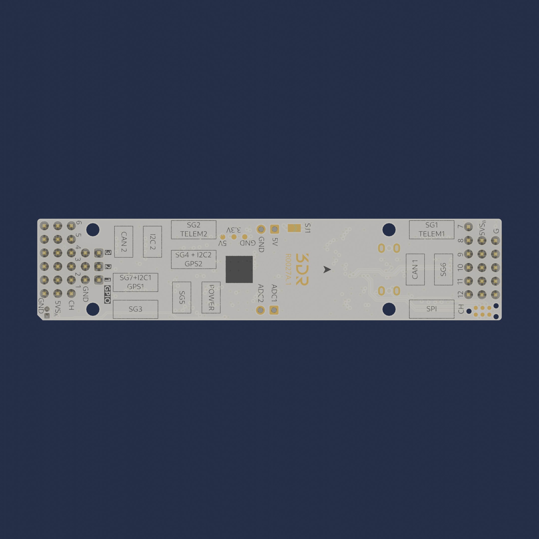
Available Ports
- USB
- GPS1 (SG7 + I2C1)
- GPS2 (SG4 + I2C2)
- Serial 1 (SG1) w/Control Flow
- Serial 2 (SG2) w/Control Flow
- Serial 3 (SG3) w/Control Flow
- Serial 5 (SG5)
- Serial 6 (SG6)
- External SPI (SPI)
- I2C2 (I2C2)
- CAN1 (CAN1)
- CAN2 (CAN2)
- POWER (PWR, ADC1 + ADC2)
- ADC1 (ADC1)
- ADC2 (ADC2)
- BOOT0 (BOOT)
- SWD CLK/IO/RST (compatible w/ TC2030 connector)
- Servos (12 x PWM, BIDIR capable)
- IOs (3x GPIO)
To have a more detailed description of each pin, please use our Pinout tool.
Pinout tool
| Port | Name | Pin |
|---|---|---|
| USB | 5V | x |
| USB | USB_DM | x |
| USB | USB_DP | x |
| USB | GND | x |
| GPS1 | 5V | 1 |
| GPS1 | UART5_TX | 2 |
| GPS1 | UART5_RX | 3 |
| GPS1 | I2C1_SCL | 4 |
| GPS1 | I2C1_SDA | 5 |
| GPS1 | GND | 6 |
| GPS2 | 5V | 1 |
| GPS2 | USART3_TX | 2 |
| GPS2 | USART3_RX | 3 |
| GPS2 | I2C2_SCL | 4 |
| GPS2 | I2C2_SDA | 5 |
| GPS2 | GND | 6 |
| SG1 | 5V | 1 |
| SG1 | USART2_TX | 2 |
| SG1 | USART2_RX | 3 |
| SG1 | USART2_CTS | 4 |
| SG1 | USART2_RTS | 5 |
| SG1 | GND | 6 |
| SG2 | 5V | 1 |
| SG2 | UART4_TX | 2 |
| SG2 | UART4_RX | 3 |
| SG2 | UART4_CTS | 4 |
| SG2 | UART4_RTS | 5 |
| SG2 | GND | 6 |
| SG3 | 5V | 1 |
| SG3 | UART7_TX | 2 |
| SG3 | UART7_RX | 3 |
| SG3 | UART7_CTS | 4 |
| SG3 | UART7_RTS | 5 |
| SG3 | GND | 6 |
| SG5 | 5V | 1 |
| SG5 | USART1_TX | 2 |
| SG5 | USART1_RX | 3 |
| SG5 | GND | 4 |
| SG6 | 5V | 1 |
| SG6 | USART6_TX | 2 |
| SG6 | USART6_RX | 3 |
| SG6 | GND | 4 |
| SPI | 5V | 1 |
| SPI | SCK | 2 |
| SPI | MISO | 3 |
| SPI | MOSI | 4 |
| SPI | CS | 5 |
| SPI | GND | 6 |
| I2C2 | 5V | 1 |
| I2C2 | SCL | 2 |
| I2C2 | SDA | 3 |
| I2C2 | GND | 4 |
| CAN1 | 5V | 1 |
| CAN1 | CAN1_H | 2 |
| CAN1 | CAN1_L | 3 |
| CAN1 | GND | 4 |
| CAN2 | 5V | 1 |
| CAN2 | CAN2_H | 2 |
| CAN2 | CAN2_L | 3 |
| CAN2 | GND | 4 |
| PWR | 5V | 1 |
| PWR | ADC1 | 2 |
| PWR | ADC2 | 3 |
| PWR | GND | 4 |
| ADC1 | ADC 1 | 1 |
| ADC2 | ADC 2 | 1 |
| BOOT | 3V3 | 1 |
| BOOT | BOOT0 | 2 |
| SWD | 5V | 1 |
| SWD | SWDIO | 2 |
| SWD | RST | 3 |
| SWD | SWDCLK | 4 |
| SWD | GND | 5 |
| SWD | NC | 6 |
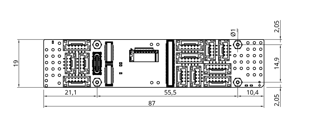
Mechanical information
| Mechanical specfications | |
|---|---|
| Dimensions | Width: 19mm (0.74″) Length: 87mm (3.42″) Height: 8.3mm (0.32") |
| Weight | 7.5g (0.27oz) |
Downloads
Maintenance
- Clean with a dry cloth; avoid moisture or abrasive materials.
- Periodically check connection points for wear or loosening.
- Store in a cool, dry place when not in use.