USB-C to Serial - M10133 
The 3DR USB-C to Serial accessory helps you to establish a connection to a RS-232 interface through your USB port, really handy for those times when you are looking a rescue or debugging tool, and also easy to use since it's out-of-the-box compliant (5V power / 3.3V logic) with a lot of Autopilots and peripherals (GNSS, Airspeed, Barometers, etc) that can communicate through a UART/USART interface.
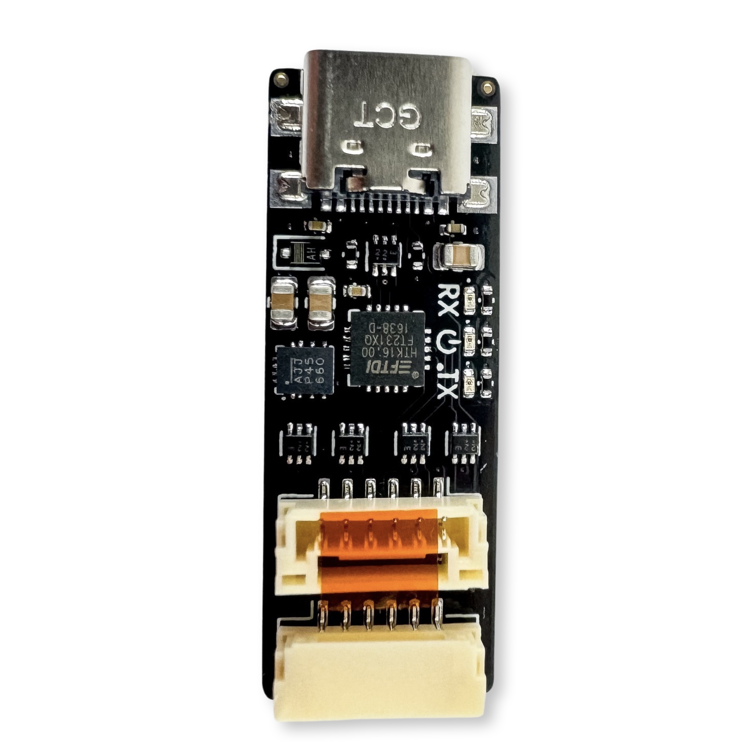
Graphical pinout diagram
Top view
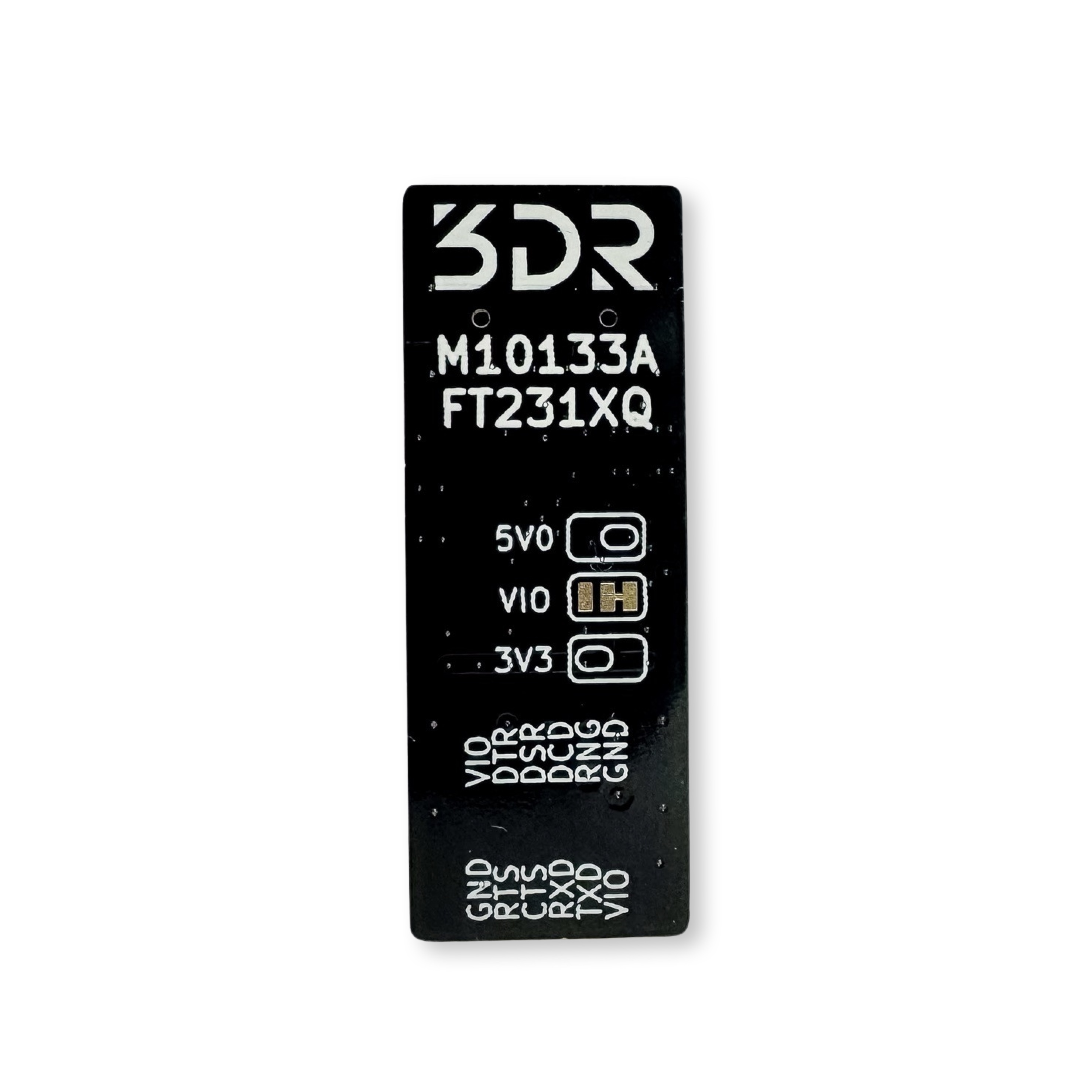
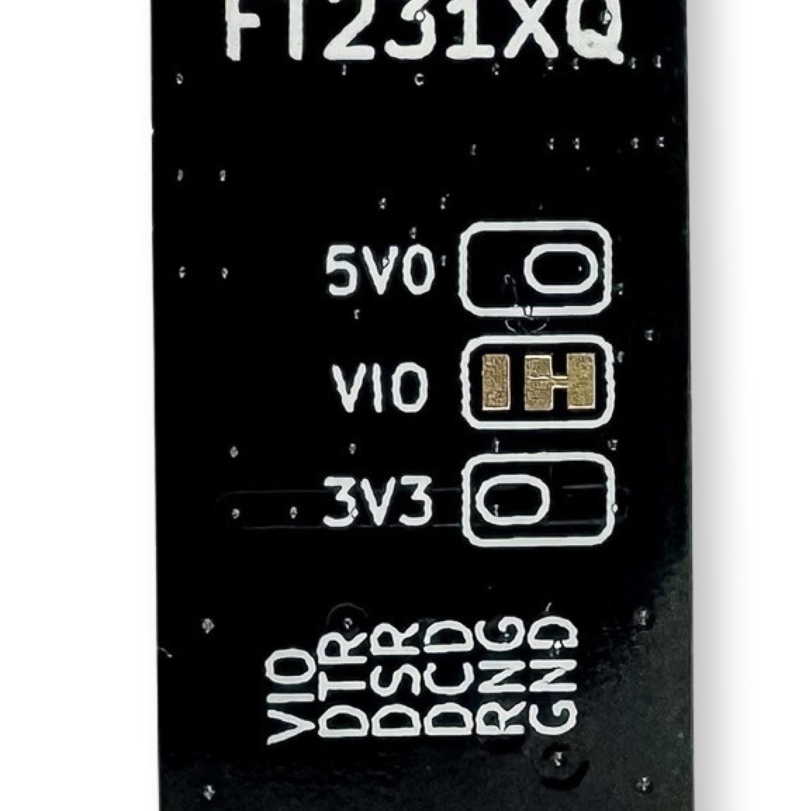
Bottom view
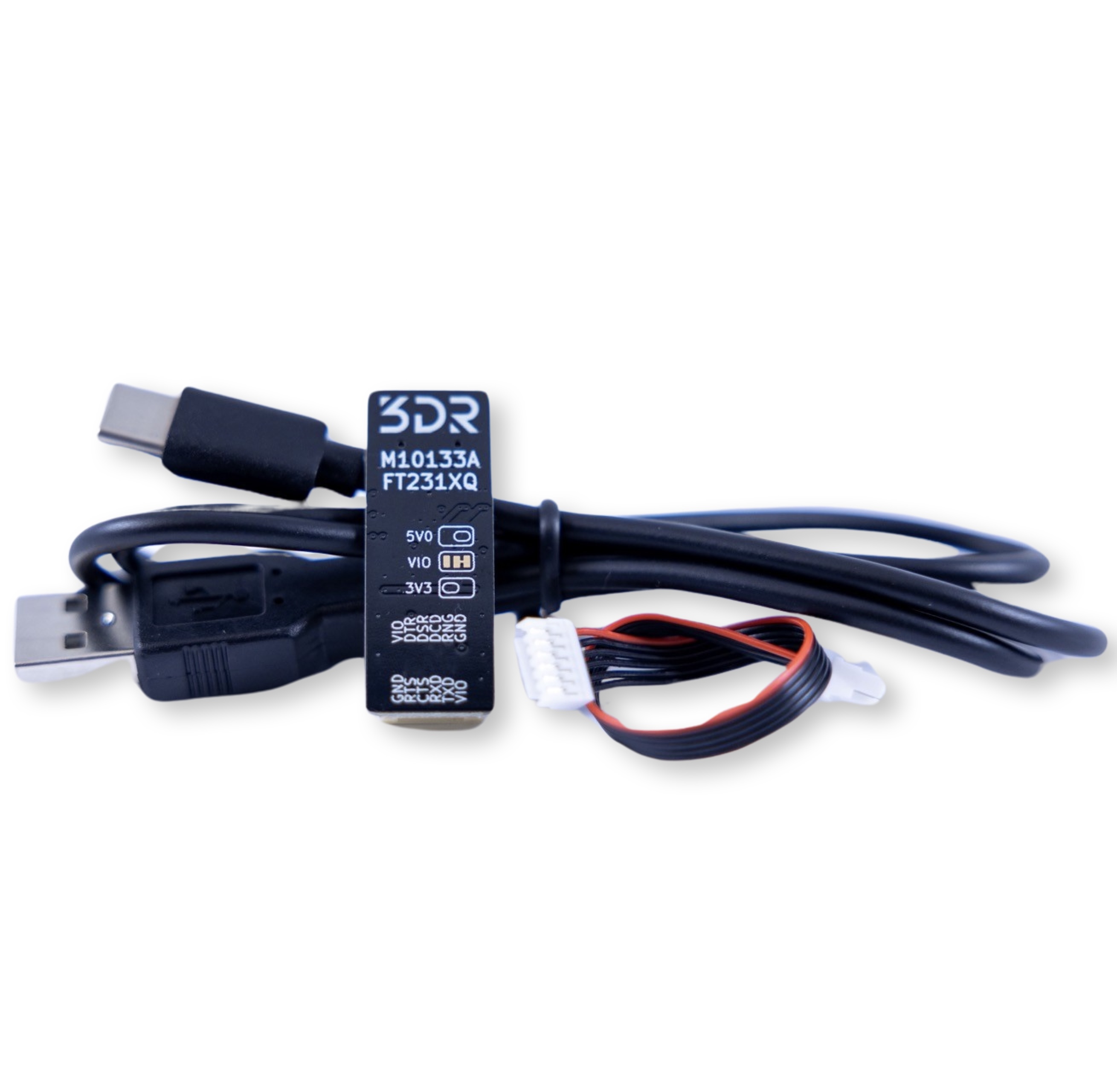
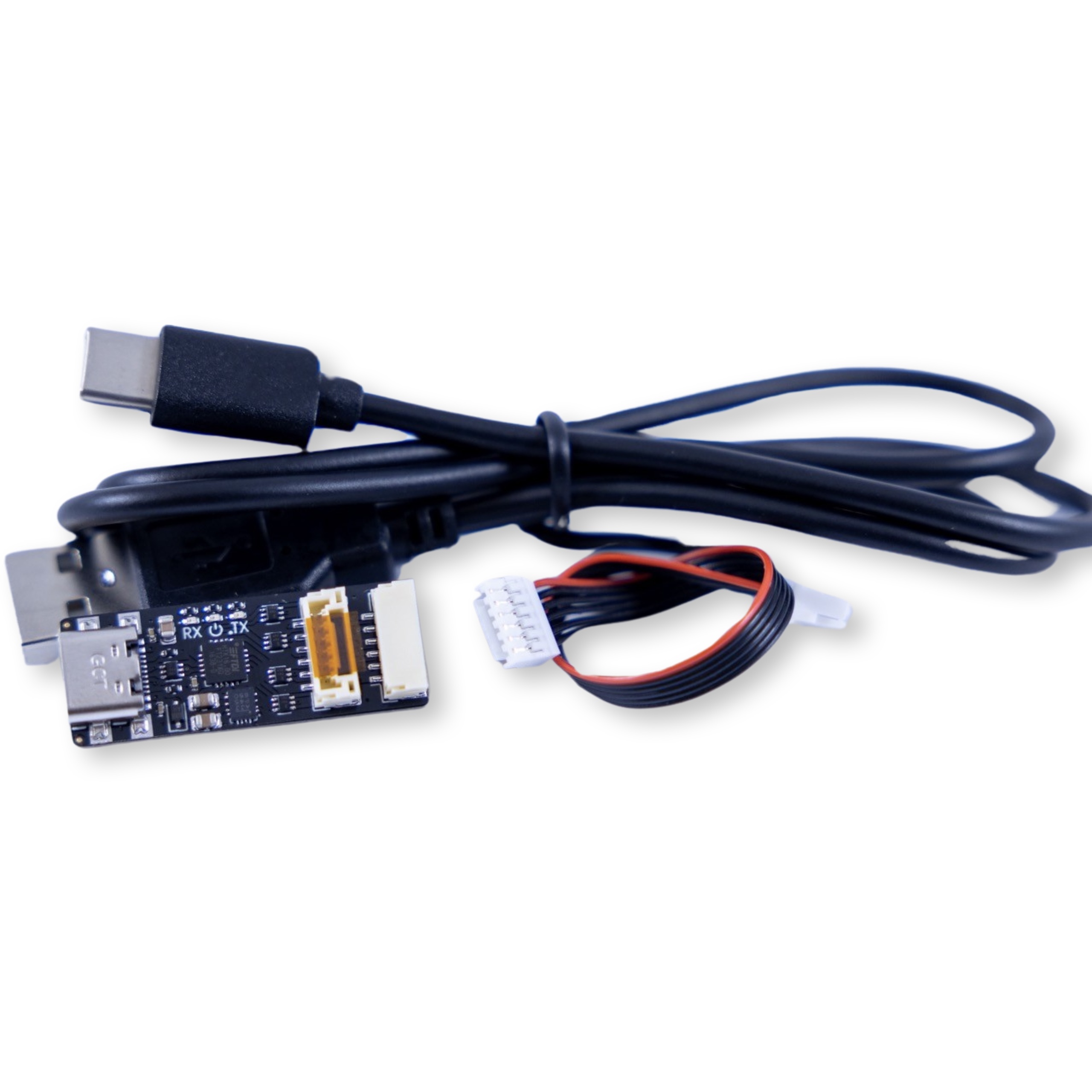
3D View
Specifications
| Electrical/MCU | USB-to-Serial M10133 |
|---|---|
| Input voltage | 5V |
| VCCIO Operating voltage | 1.62 - 3.63 V |
| Maximum current | 3A |
| Output voltage | 5V, 3.3V, selectable |
| Mechanical | |
|---|---|
| Dimensions | 35mm x 13 mm |
| Screw pattern | X |
| Screw size | M3 (3.2mm hole diameter) |
Changelog
- Revision A
Quick Start
- Connect the connector to the respective serial port, make sure to verify that the pins match accordingly to what is shown on the label. Also figure out which power source is more convenient for your device, read Selecting power source for further information.
- Connect your USB C cable into your PC
- Have fun!
Note
In case that you need to establish communication with your Autopilot, make sure to cross the right lines (TX with RX, RTS with CTS and DTR with DTS).
Port pinout tables
J1 Connector
| Pin | Color | Signal | TTL/Voltage Level |
|---|---|---|---|
| 1 | red | VIO | 5V (Default1) |
| 2 | black | TXD | 3V3 |
| 3 | black | RXD | 3V3 |
| 4 | black | CTS | 3V3 |
| 5 | black | RTS | 3V3 |
| 6 | black | GND | GND |
J2 Connector
| Pin | Color | Signal | TTL/Voltage Level |
|---|---|---|---|
| 1 | red | VIO | 5V (Default1) |
| 2 | black | DTR | 3V3 |
| 3 | black | DSR | 3V3 |
| 4 | black | DCD | 3V3 |
| 5 | black | RI | 3V3 |
| 6 | black | GND | GND |
Selecting power source
Danger
Pin 1 (VIO) voltage will have different power characteristics depending on user's selection, which can be set by manipulating the solder jumper pad located at the bottom. By default, power is provided by USB (5V), to select 3V3, the user needs to cut the trace and add a solder joint to 3V3 selection. Please take in account that it will provide 3V3 and up to 0.6A. The user can find a visual guide next to the solder joint. Where VIO is connected to any or the power selections (not both). To return to default settings, a solder joint should be connected back to 5V.
Downloads
Drivers
- Windows 10/11 (32/64 bit, 64 bit) FTDI driver
- Linux (already part of the main kernel)
-
Please read Selecting power source for further information ↩↩